
Self-sealing mattress structure

Inactive Publication Date: 2005-01-11
HILL ROM SERVICES
View PDF84 Cites 25 Cited by
  • Summary
  • Abstract
  • Description
  • Claims
  • Application Information

AI Technical Summary

Benefits of technology

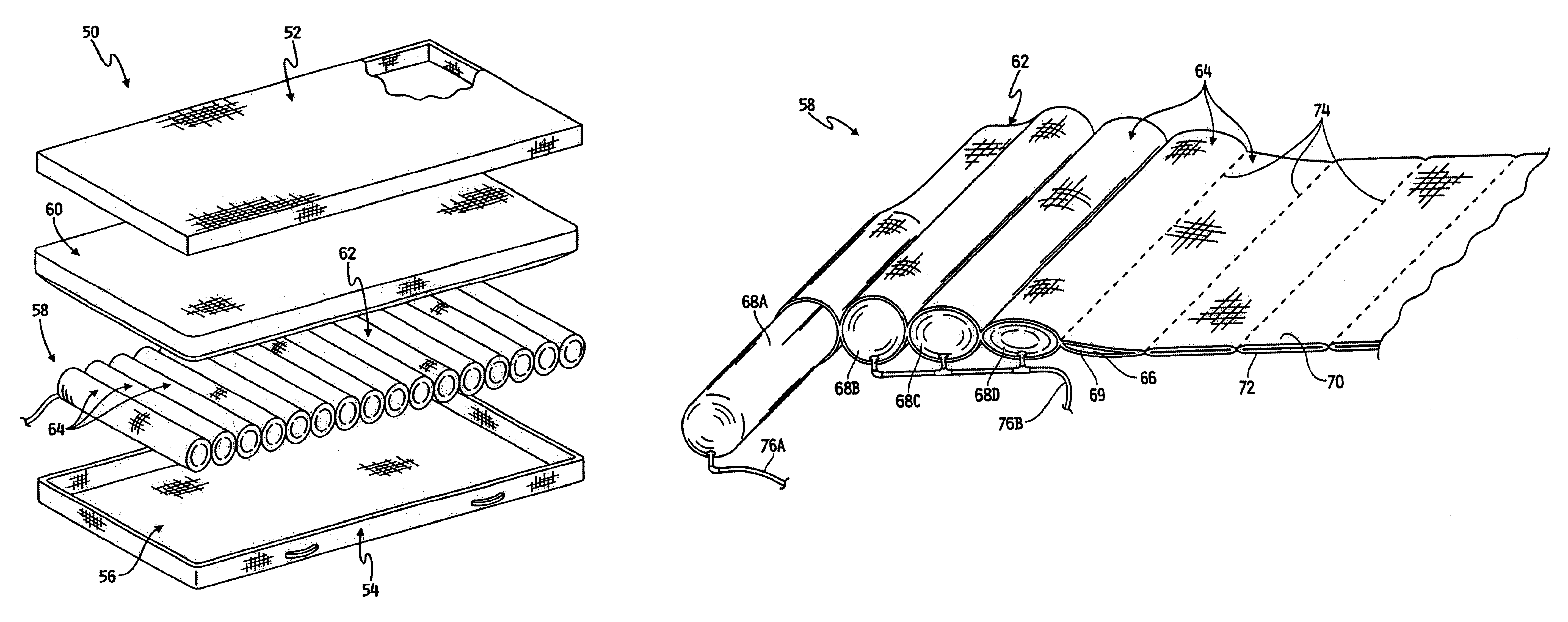
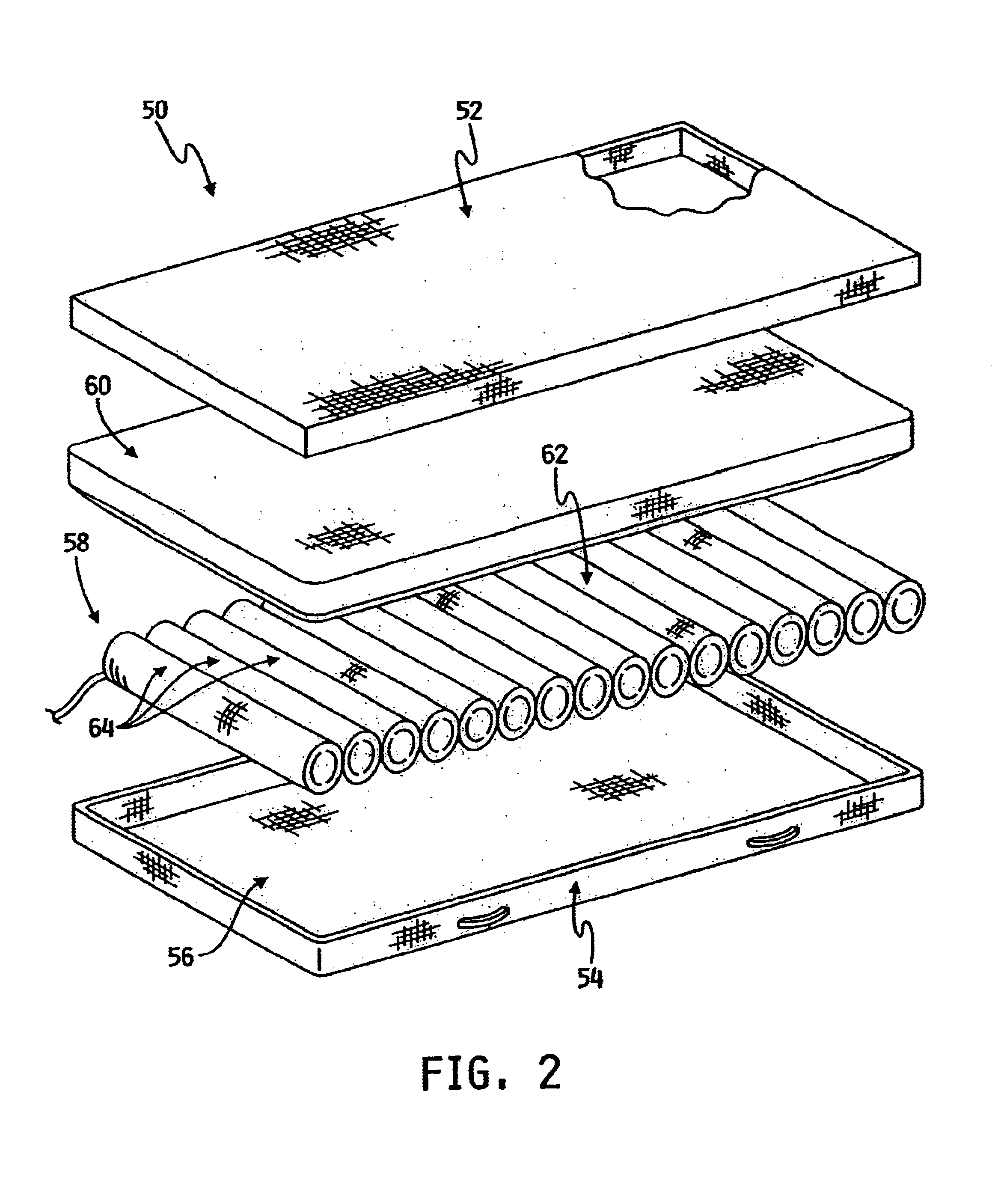
The present invention provides a mattress for a bed having siderails, including a relatively thin, non-puncture resistant cover having an interior surface, and a core disposed adjacent the interior surface of the cover. The core includes a body that defines a plurality of gas enclosures with self-sealing characteristics. In one embodiment of the invention, the body includes a core that defines the plurality of gas enclosures that function as mounting locations for a plurality of self-sealing gas containers respectively disposed within the plurality of mounting locations. The core may further include an upper layer and a lower layer, connected together at a plurality of substantially parallel seams, thereby forming a plurality of substantially cylindrical mounting locations. The plurality of self-sealing gas containers, in this embodiment, may be formed as substantially cylindrical inflatable tubes, which are respectively disposed in the cylindrical mounting locations. The air containers may be pressurized by a gas source such as an air compressor. In the event of a puncture, the gas containers automatically re-seal as a result of the self-sealing material of the containers, thereby eliminating the need for a foam layer, and avoiding the loss of performance resulting from the use of a protective foam layer.
In another embodiment of the invention, the gas enclosures defined by the core body may include a self-sealing lining. In this embodiment, the core may also include an upper layer and a lower layer, connected together at a plurality of substantially parallel seams, to thereby form the gas enclosures. In the event of a puncture, the gas enclosure lining re-seals the gas enclosure, thereby eliminating the need for a foam layer and the associated loss of performance.

Problems solved by technology

In the event of a puncture, the gas enclosure lining re-seals the gas enclosure, thereby eliminating the need for a foam layer and the associated loss of performance.

Method used


Image

  • Self-sealing mattress structure
  • Self-sealing mattress structure
  • Self-sealing mattress structure

Examples


Embodiment Construction

The embodiments selected for description were not selected to limit the invention to the precise forms disclosed. Instead, the embodiments were selected to illustrate the concepts of the invention and to enable one of ordinary skill in the art to practice the invention.

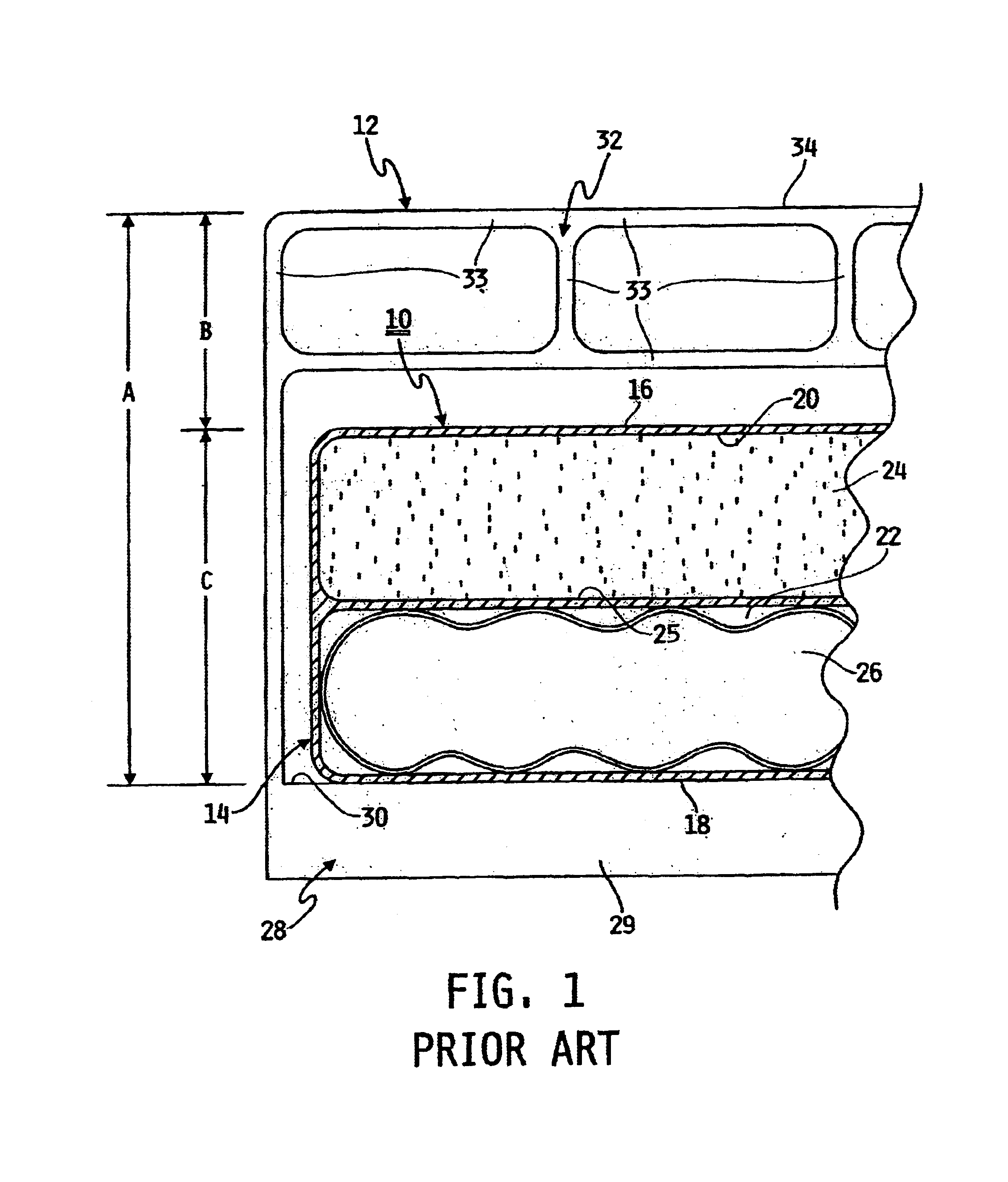
Referring now to FIG. 1, a conventional mattress structure 10 is shown situated on a conventional hospital bed 12. Mattress structure 10 generally includes an enclosure 14 having an upper, sleep surface 16, a lower surface 18, and defining an upper chamber 20 and a lower chamber 22. Chambers 20, 22 may be divided into a plurality of sub-chambers (not shown) by a plurality of interior walls (not shown). Upper chamber 20 is separated from lower chamber 22 by a dividing wall 25. In conventional mattress structure 10, upper chamber 20 contains a foam layer 24, and lower chamber 22 contains an inflatable layer 26. Foam layer 24 may include a plurality of foam cylinders or other shapes (shown as one solid foam piece in FIG....


PUM


Abstract

A mattress for a bed having a frame for supporting the mattress and side rails, includes a non-puncture resistant cover with an interior surface, and a core disposed adjacent the interior surface. The core includes a body defining a plurality of mounting locations, and further includes a plurality of self sealing gas containers that are respectively disposed within the plurality of mounting locations. Accordingly, the overall height of the mattress may be used by the gas containers since a puncture resistant foam layer is not necessary.

Description

FIELD OF THE INVENTIONThe present invention generally relates to a mattress structure, and more particularly to a mattress structure for hospital beds having a core with a plurality of self-sealing gas enclosures.BACKGROUND OF THE INVENTIONMattress support structures for health care applications, such as hospital beds, are generally provided with a mattress having air cushions. It is desirable to provide a mattress with air cushions that are as thick or tall as possible to provide maximum comfort and maximum mattress performance. The height of conventional air mattress are limited, however, by regulatory requirements relating to the minimum bed siderail height above the sleep surface of the mattress. In typical applications, the bed siderail height regulations effectively limit the overall mattress height to approximately six inches. A portion of this overall mattress height is used by a layer of foam or similar material placed on top of the air cushions. In health care settings, th...

Claims


Application Information

Patent Timeline
IPC IPC(8): A47C27/00A47C27/10
CPCA47C27/001A47C27/18A47C27/10A47C27/082
Inventor STOLPMANN, JAMES R.
Owner HILL ROM SERVICES
Learn More