Kiln cleaning apparatus

a technology for cleaning equipment and kilns, which is applied in the direction of mechanical equipment, light and heating equipment, hollow article cleaning, etc., can solve the problems of affecting the efficiency and production performance of the kiln, recurring accumulation of particulate deposits on the inner refractory lining of the kiln, and deposits on the interior surfaces of the kiln

Inactive Publication Date: 2005-01-11
MARTIN ENG
View PDF9 Cites 5 Cited by
  • Summary
  • Abstract
  • Description
  • Claims
  • Application Information

AI Technical Summary

Benefits of technology

This patent describes how to create a device that can constantly spray out pressure liquid through its entire movement. It does this by making sure that a layer of material called a sleeve is tightly connected to the main part of the machine (the drill shaft). Pressure liquid flows into the system from one end of the sleeve and moves along it until it reaches another area inside the drshaft where it comes back out again. By spinning this process over and over, the device makes sure that always has something new to spray every time it moves.

Problems solved by technology

The technical problem addressed in this patent text is the accumulation of particulate deposits on the inner refractory lining of industrial kilns, particularly cement kilns, which can cause damage to the refractory lining and decrease efficiency and production performance of the kiln. Current methods for removing the deposits, such as pneumatic blasting and carbon dioxide explosions, require access to the interior of the kiln and are reactionary to the buildup problem. Additionally, the buildup can encrust and block access ports, requiring additional equipment and manpower to clean the kiln. The patent aims to provide a solution to this problem by introducing a new method for preventing and eliminating particulate buildup on the refractory lining of industrial kilns.

Method used


Image

  • Kiln cleaning apparatus
  • Kiln cleaning apparatus
  • Kiln cleaning apparatus

Examples


Embodiment Construction

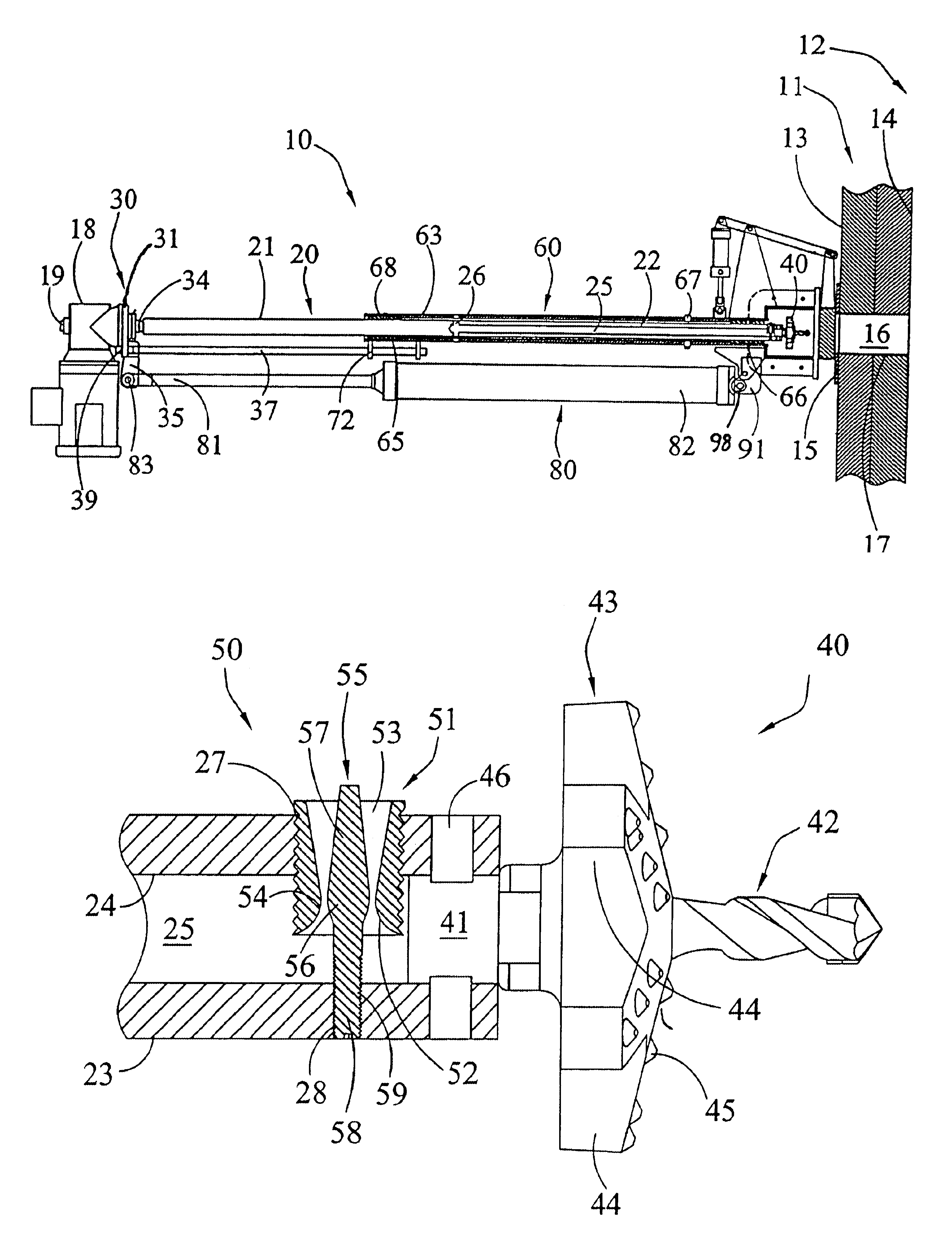
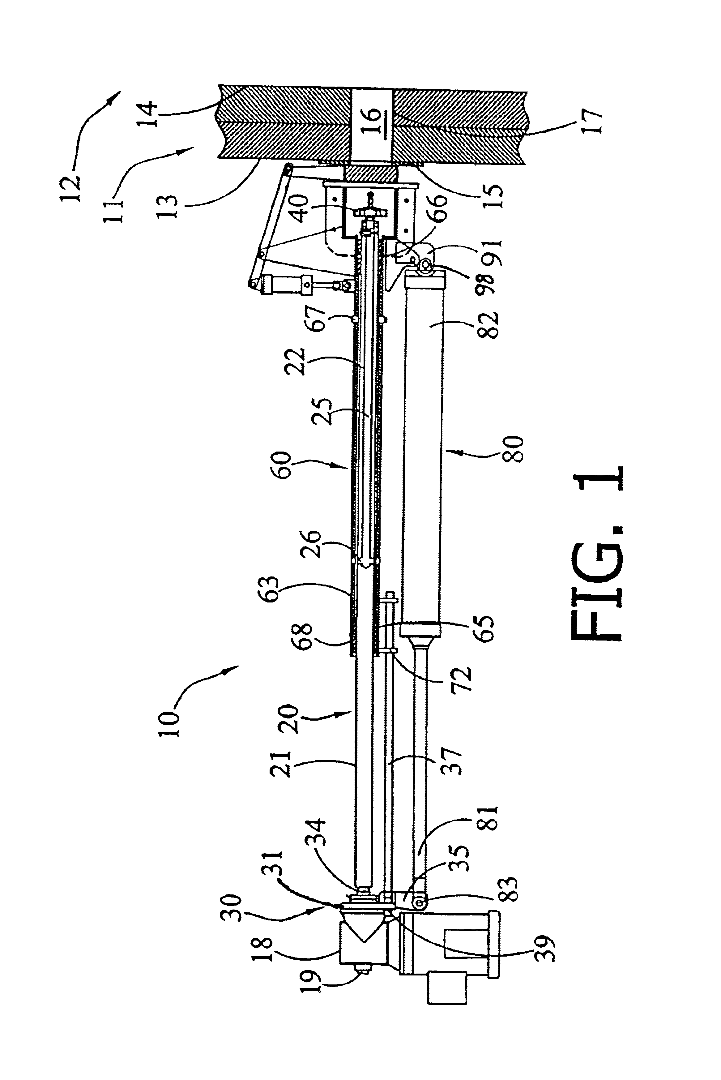
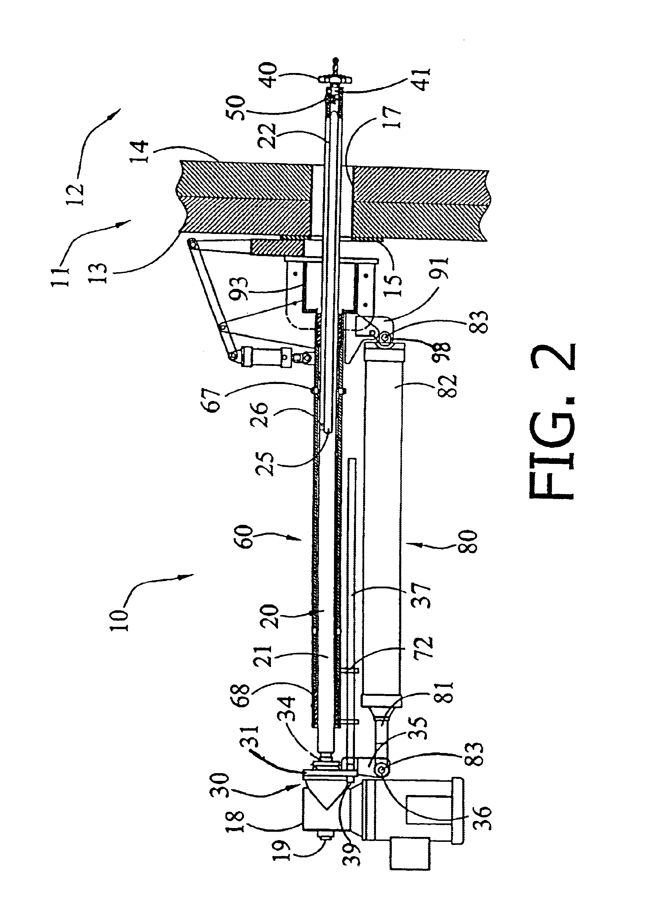
Referring to the drawings for a more complete description of the invention the kiln cleaning apparatus 10 is shown mounted to a wall 11 of an industrial kiln 12. Kiln wall 11 includes a duct wall 13 and a refractory lining 14. An industrial kiln 12 may include a plurality of access ports 16 spaced apart throughout wall 11 permitting access to the interior of kiln 12 for cleaning deposits which have accumulated on refractory lining 14 during operation of kiln 12. Each access port 16 will typically include a protective sleeve 17 to prevent damage to refractory lining 14. Support for protective sleeve 17 is provided by a flange 15, which is secured to wall 11.

As may be seen in FIG. 1, the cleaning apparatus 10 comprises a rotary drive unit 18 with its output shaft 19 operatively connected to a first end 21 of a drill shaft 20, via a coupling unit 30. Coupling unit 30 includes a coupling plate 31, a bearing 33, and a bearing retainer 34. Coupling unit 30 is attached to rotary drive unit...


PUM


Abstract

An apparatus for cleaning deposits from the interior surfaces of a kiln. The apparatus utilizes a directed high-pressure fluid jet to remove deposits adhering to elements within a kiln. The pressurized fluid is delivered to the fluid jet through the shaft of a rotary drill. The drill shaft is received in a sleeve permitting rotational and longitudinal displacement of the shaft. The sleeve also defines a plenum surrounding the drill shaft to communicate pressurized fluid to the fluid jet throughout longitudinal and rotational displacement of the drill shaft. The drill further utilized a boring bit suitable for penetrating encrusted deposits to provide the fluid jet access to the interior surfaces of the kiln. For removing severe encrustations, the drill bit may be used to partially penetrate the encrustation and a linear actuator may then be employed to press large portions of the encrustation from the kiln's refractory lining.

Description


Claims


Application Information

Patent Timeline
Owner MARTIN ENG
Why Eureka
Try Eureka