High-heat transfer low-NOx combustion system

a combustion system and high heat transfer technology, applied in combustion types, combustion of lump and pulverulent fuel, lighting and heating apparatus, etc., can solve the problems of uncontrolled increasing raw material volatilization and uncontrollable emissions of nitrogen oxides, sulfur oxides and process particulates, etc., to avoid the generation of hot spots, reduce nox emissions, and uniform heat distribution

Active Publication Date: 2005-09-06
GAS TECH INST
View PDF7 Cites 69 Cited by
  • Summary
  • Abstract
  • Description
  • Claims
  • Application Information

AI Technical Summary

Benefits of technology

[0011]It is another object of this invention to provide a combustion system which, in addition to producing a highly luminous flame, generates lower NOx emissions than conventional high luminosity flame combustion systems.
[0012]It is another object of this invention to provide a combustion system which, in addition to producing a highly luminous flame and generating lower NOx emissions, is also suitable for retrofitting.
[0013]It is still a further object of this invention to provide a combustion system which provides substantially uniform heat distribution and avoids the generation of hot spots within the furnace to which it is applied.

Problems solved by technology

However, conventional burners that produce generally conical flames have the undesirable tendency to produce hot spots within the furnace, resulting in furnace refractory damage, particularly to furnace crowns or roofs and sidewalls which are opposite the flame.
Such conventional burners also cause increased raw material volatilization and uncontrolled emissions of nitrogen oxides, sulfur oxides and process particulates.
To address some of the problems associated with such designs, conventional burners have incorporated low momentum flow, which is produced by the use of relatively lower fuel and oxygen velocities, resulting in relatively lower momentum flames.
Such lower velocities and, thus, lower momentums result in longer flames and increased load coverage.
However, undesirable flame lofting occurs at such lower velocities, causing undesirable effects.
However, this staggered firing arrangement often creates undesirable cold regions in pocket areas between adjacent burners.
However, increasing the number of burners also undesirably significantly increases the installation and operation costs.

Method used


Image

  • High-heat transfer low-NOx combustion system
  • High-heat transfer low-NOx combustion system
  • High-heat transfer low-NOx combustion system

Examples


Embodiment Construction

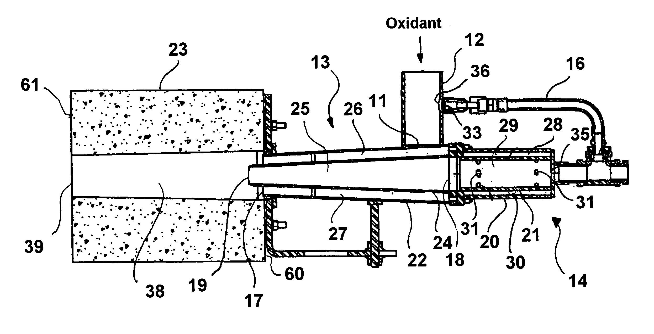
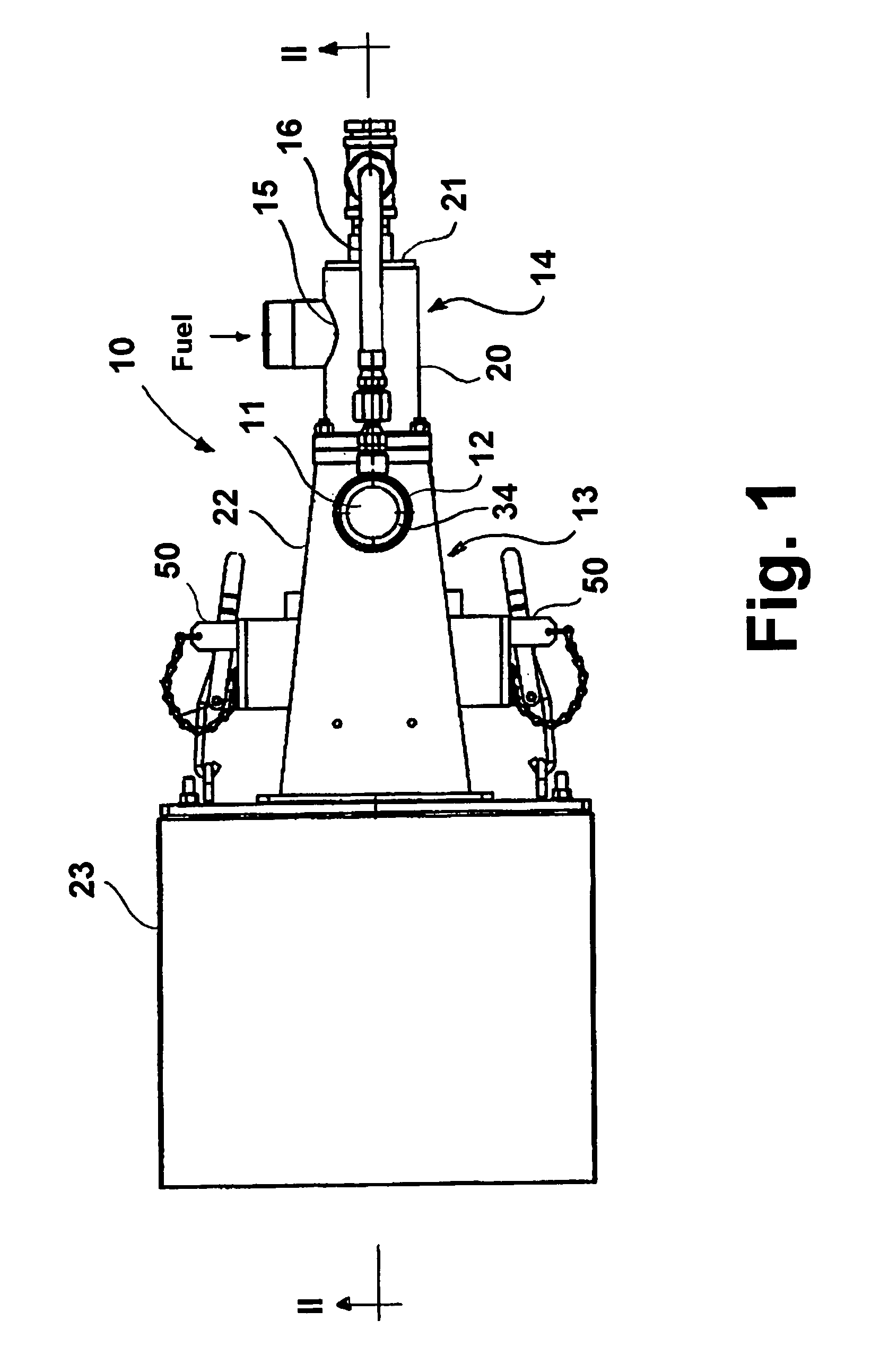
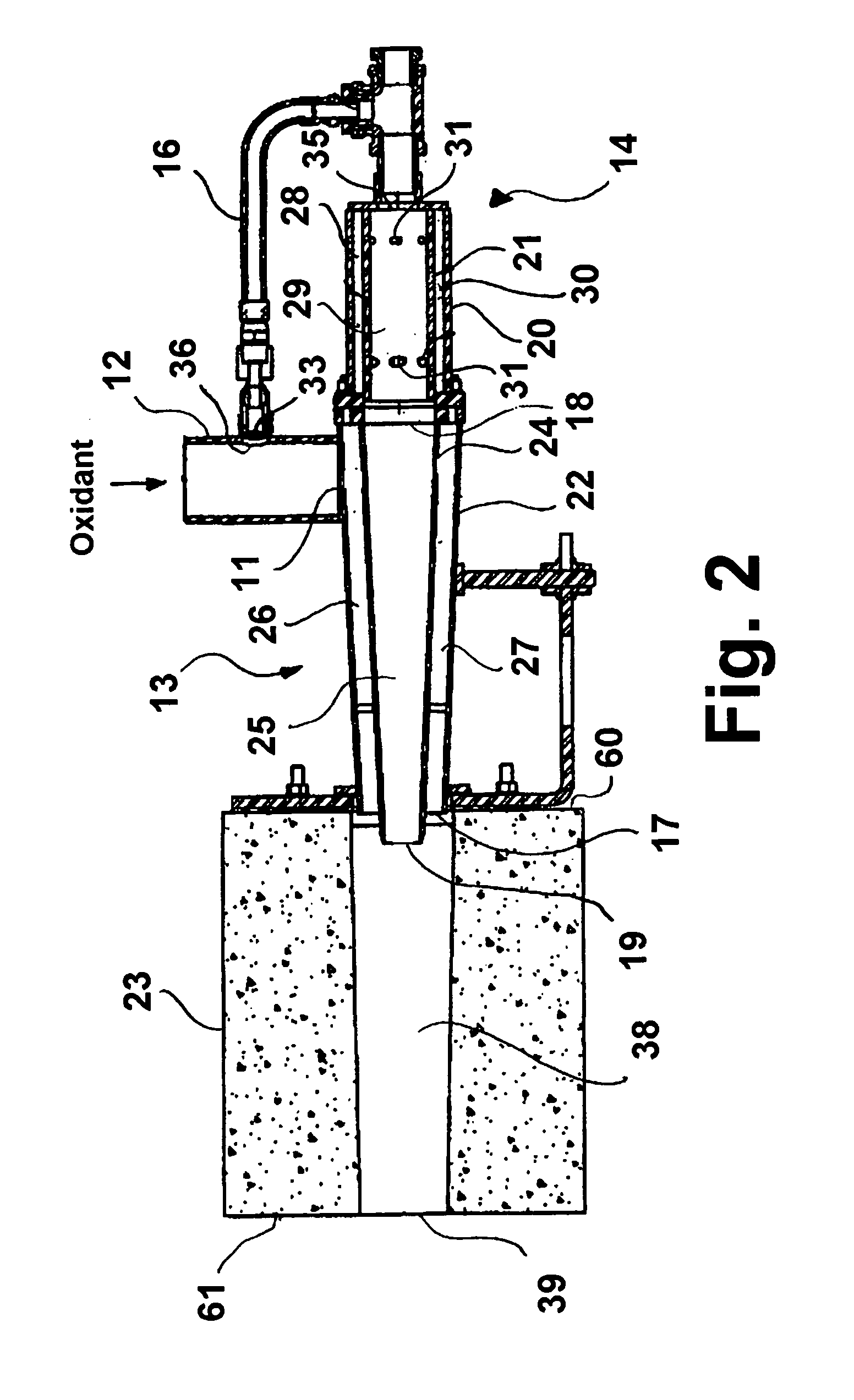
[0020]Referring to FIGS. 1 and 2, the combustion system 10 of this invention comprises three basic components or stages—primary combustion stage 13, pre-combustor stage 14 disposed upstream of primary combustion stage 13 and burner or refractory block 23 disposed downstream of primary combustion stage 13. As used herein, the terms upstream and downstream apply generally to the direction of flow of fuel and oxidant through the system, which in FIGS. 1 and 2 is from right to left.

[0021]Primary combustion stage 13 comprises at least one outer wall 22 forming an oxidant chamber 26 having a primary oxidant inlet 11 connected to an oxidant supply conduit 12 and having a primary oxidant outlet 17. Disposed within the oxidant chamber 26 is at least one inner wall 24 forming a fuel chamber 25 having a primary fuel inlet 18, a primary fuel outlet 19 oriented in the direction of the primary oxidant outlet 17 and forming a primary annular space 27 between the at least one outer wall 22 and the ...


PUM


Abstract

A combustion apparatus comprising a pre-combustor stage and a primary combustion stage, the pre-combustor stage having two co-axial cylinders, one for oxidant and one for fuel gas, in which the fuel gas is preheated and the primary combustion stage having rectangular co-axial passages through which fuel and oxidant are admitted into a refractory burner block. Both passages converge in the vertical plane and diverge in the horizontal plane. The passage through the refractory burner block also has a rectangular profile and diverges in the horizontal plane. The outlets to the primary combustion stage are recessed in the refractory burner block at a distance which may be varied.

Description

[0001]The U.S. Government has a paid-up license in this invention and the right in limited circumstances to require the patent owner to license others on reasonable terms as provided for by the terms of Contract No. DE-FC02-95CE41185 awarded by the U.S. Department of Energy.BACKGROUND OF THE INVENTION[0002]1. Field of the Invention[0003]This invention relates to combustion systems employing burners that produce highly luminous flames, thereby providing higher heat transfer and lower NOx emissions than conventional combustion systems. More particularly, this invention relates to a method and apparatus for producing substantially flat flames which produce uniform heat distribution and relatively high radiative heat transmission. Burners employed in the combustion systems of this invention preferably use oxygen or oxygen-enriched air as an oxidant, although air may also be used.[0004]2. Description of Related Art[0005]Environmental requirements have been and continue to be a major impe...

Claims


Application Information

Patent Timeline
Patent Type & Authority Patents(United States)
IPC IPC(8): F23D14/20F23D14/00F23C6/04F23C6/00F23D14/32F23D99/00
CPCF23C6/042F23D14/20F23D14/32F23D2209/10Y02E20/344
Inventor ABBASI, HAMID A.HOBSON, JR., WILLIAM J.RUE, DAVID M.SMIRNOV, VALERIY
Owner GAS TECH INST
Why Eureka
Try Eureka