
Fuel spud for high temperature burners

a burner and high temperature technology, applied in the direction of burner ignition devices, combustion types, lighting and heating apparatuses, etc., can solve the problems of nox burners, less desirable alternatives to burner design improvements, and high cost, so as to reduce nox emissions, reduce nox emissions, and increase the inspiratory

Inactive Publication Date: 2005-05-17
EXXONMOBIL CHEM PAT INC
View PDF83 Cites 16 Cited by
  • Summary
  • Abstract
  • Description
  • Claims
  • Application Information

AI Technical Summary

Benefits of technology

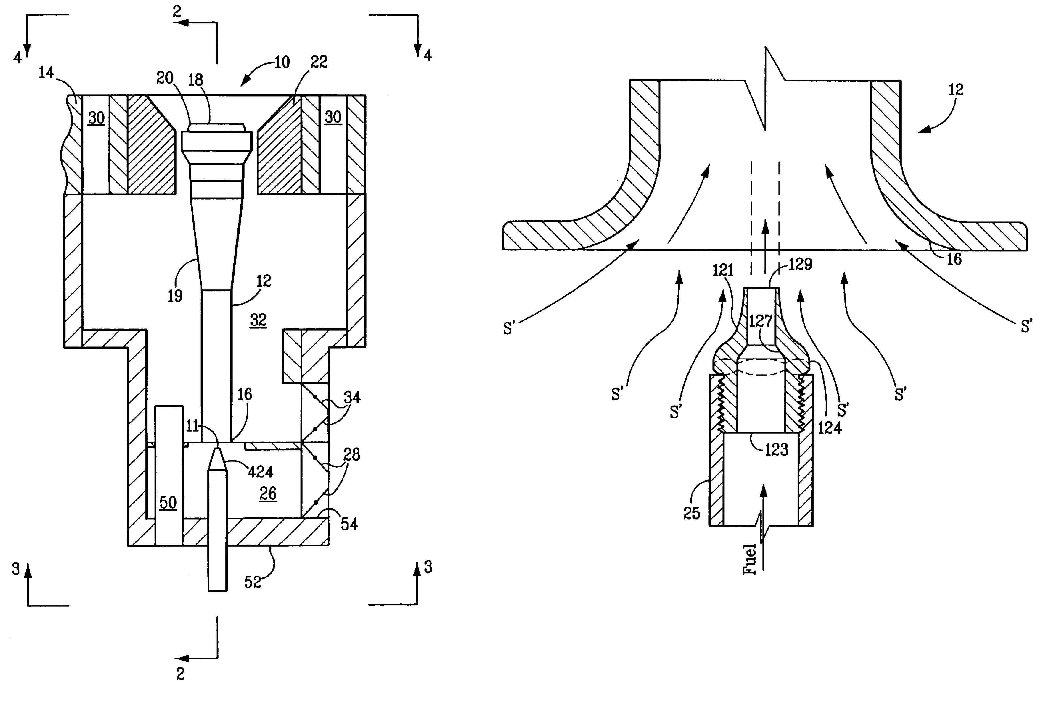
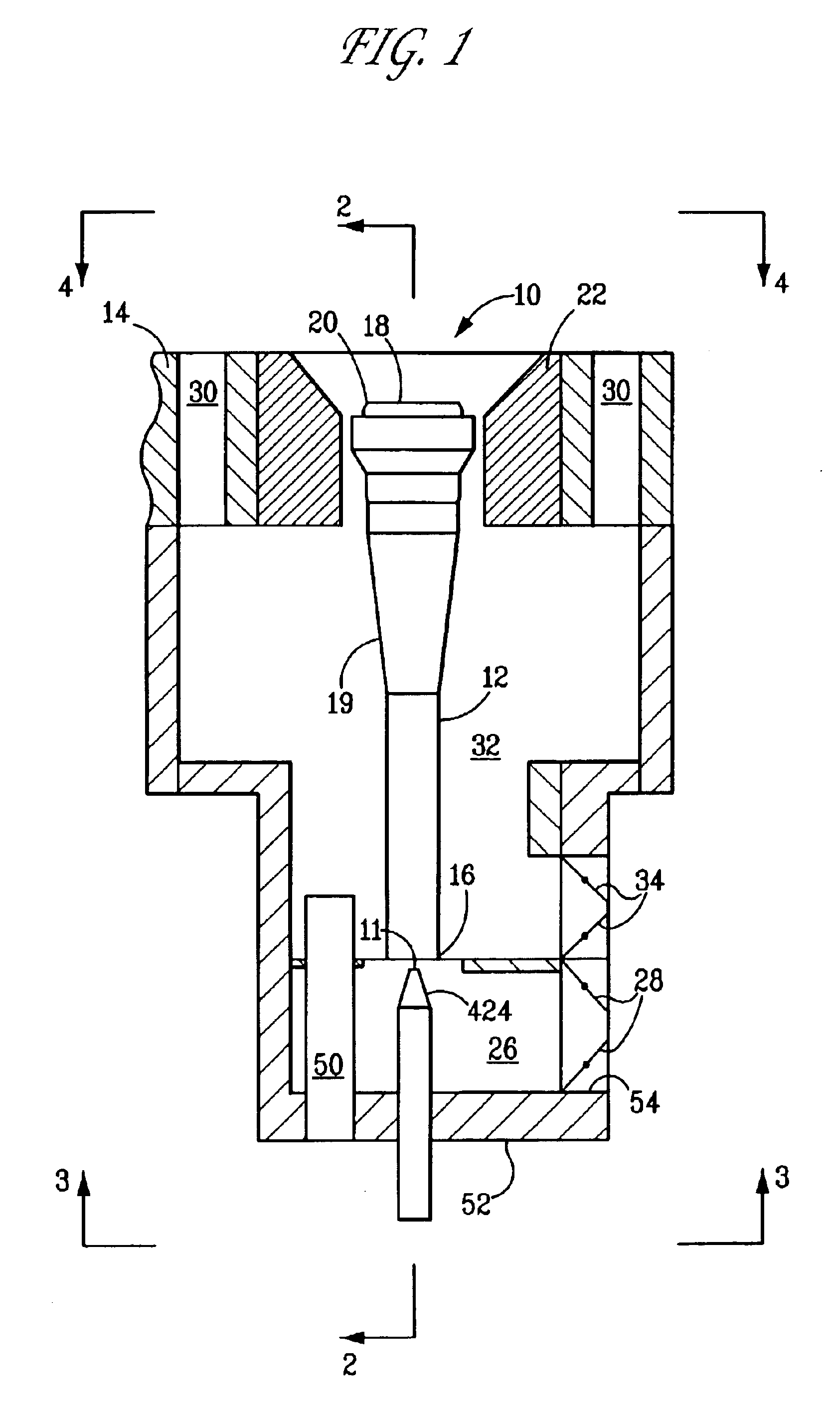
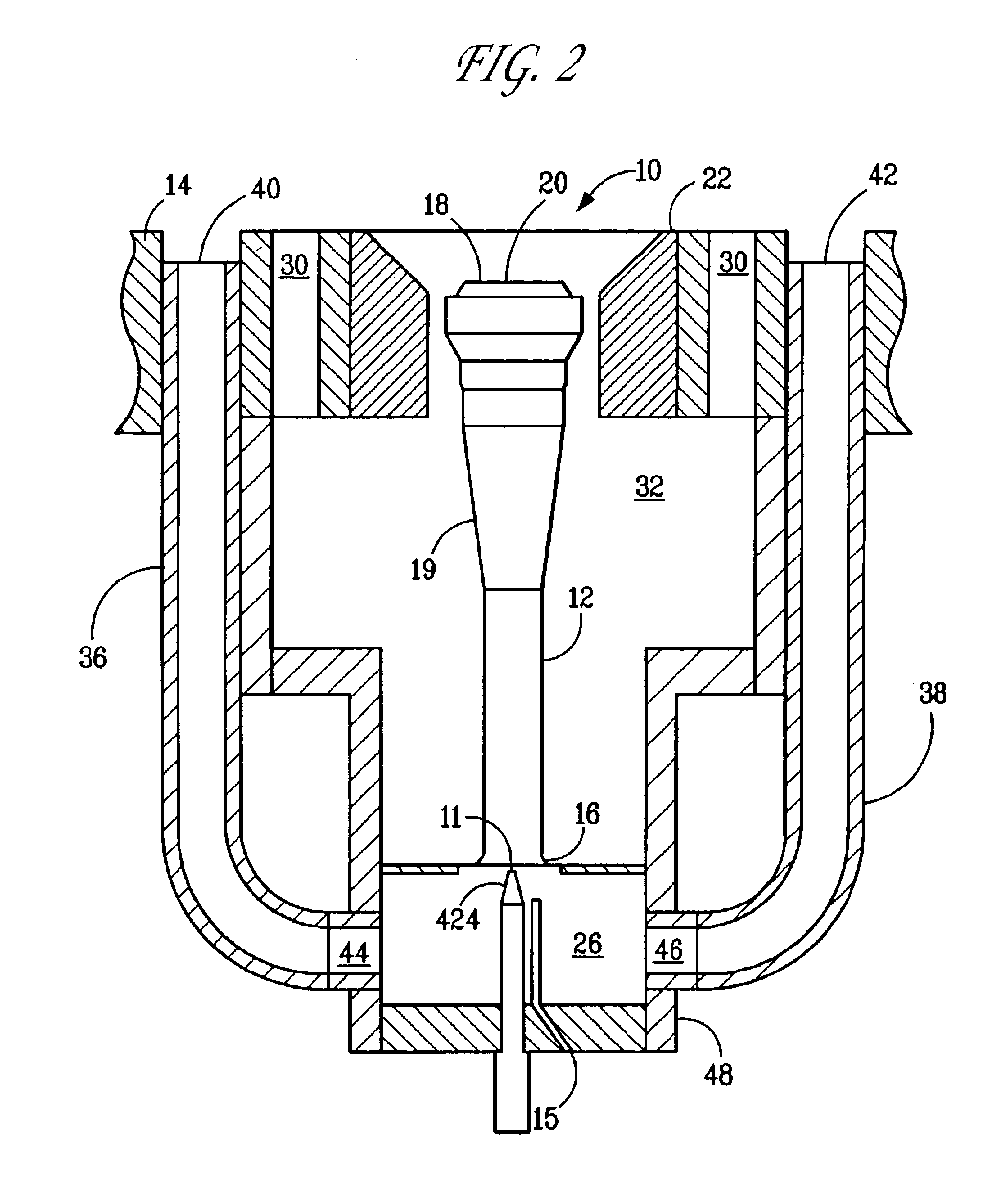
[0022]The present invention is directed to an improved low NOx burner and to a method for reducing NOx emissions from burners used in furnaces such as those found in steam cracking. The burner includes a burner tube having a downstream end and having an upstream end, the burner tube having a venturi therein; a fuel spud located adjacent the upstream end of the burner tube, for introducing fuel gas into the burner tube; a burner tip mounted on the downstream end of the burner tube adjacent a first opening in the furnace; at least one passageway having a first end and a second end adjacent the upstream end of the burner tube; means for drawing flue gas from the furnace, through the passageway, in response to an inspirating effect of uncombusted fuel gas exiting the fuel spud, the uncombusted fuel gas flowing through the burner tube from its upstream end towards its downstream end; and means for increasing the inspirating effect of uncombusted fuel gas exiting the fuel spud. The means for increasing the inspirating effect of uncombusted fuel gas exiting the fuel spud is effective to increase the amount of flue gas drawn from the furnace prior to the zone of combustion over a burner without the means for increasing the inspirating effect, resulting in lower NOx emissions during combustion over a similar burner utilizing a conventional fuel spud design.
[0023]The method of the present invention includes the steps of combining fuel gas, air or mixtures thereof at a predetermined location adjacent a fuel spud; discharging the fuel gas, air or mixtures thereof at a burner tip downstream of the predetermined location, the burner tip surrounded by a peripheral tile; drawing a stream of flue gas from the furnace in response to the inspirating effect of uncombusted fuel gas exiting the fuel spud and flowing towards the combustion zone, the flue gas mixing with fuel or fuel and air at the predetermined location upstream of the zone of combustion; increasing the inspirating effect of uncombusted fuel gas exiting the fuel spud; and combusting the fuel gas downstream of the burner tip downstream of the predetermined location, wherein the inspirating increasing step is effective to increase the amount of flue gas drawn from the furnace.
[0024]An object of the present invention is to provide a burner configuration wherein higher levels of flue gas recirculation may be achieved, yielding further reductions in NOx emissions.
[0025]A further object of the present invention is to optimize the gas exit velocity of the fuel spud to increase the inspiration efficiency of the fuel spud / burner tube venturi combination.
[0026]A yet further object is to provide a fuel gas control system capable of maximizing the benefits resulting from the use of a converging / diverging nozzle fuel spud.

Problems solved by technology

However, the reaction takes time and a mixture of nitrogen and oxygen at a given temperature for a very short time may produce less NOx than the same mixture at a lower temperature, over a longer period of time.
This strategy, known as Selective Catalytic Reduction (SCR), is very costly and, although it can be effective in meeting more stringent regulations, represents a less desirable alternative to improvements in burner design.
In addition, many raw gas burners produce luminous flames.
However this must be balanced with the fact that radiant heat transfer decreases with reduced flame temperature, while carbon monoxide (CO) emissions, an indication of incomplete combustion, may actually increase as well.
In addition, the fuel nozzles of such burners are generally exposed to the high temperature flue-gas in the firebox.
In the high temperature environment of steam-cracking furnaces used for the manufacture of ethylene, the combination of small diameter fuel nozzles and exposure to high temperature flue gas can lead to fouling and potential plugging of the fuel jets.
This not only has an adverse impact on burner performance, but also increases the cost of maintenance associated with repeated cleaning of fuel nozzles.
An additional challenge to the designer of industrial burners is to find techniques for meeting the increasingly stringent emission standards for NOx.
Burners of the type disclosed in U.S. Pat. No. 5,092,761, while effective in reducing NOx emissions over other designs, have generally exhibited an inability to increase levels of flue gas recirculation beyond ten percent, limiting their ability to achieve further reductions in NOx emissions.

Method used


Image

  • Fuel spud for high temperature burners
  • Fuel spud for high temperature burners
  • Fuel spud for high temperature burners

Examples


example 1

[0081]The following example demonstrates that using a converging / diverging Laval nozzle fuel spud can increase gas velocity (and hence momentum). The following burner condition was studied: fuel rate=348 lb. / hr; fuel composition=CH4; fuel upstream temperature=60° F.; fuel upstream pressure=50 psig. A fuel spud throat diameter=0.3360 inch was selected. Three different nozzle outlet diameters were evaluated for their impact on exit pressure and exit velocity. The results of the analysis follow:

[0082]

Gas Pressure atGas Velocity atNozzle Exhaust DiameterNozzle ExitNozzle Exit0.3855 inches 0.0 psig2,014 ft / sec0.3611 inches 5.0 psig1,833 ft / sec0.3467 inches10.0 psig1,670 ft / sec

[0083]As may be seen, the highest gas velocity achievable occurred at a nozzle exhaust diameter of 0.3855 inches (gas exit pressure=0.0 psig). This increase in velocity and momentum directionally improves the inspirating capability of the fuel spud / venturi combination, permitting the FGR ratio to be increased on a b...

examples 2-4

[0084]These examples demonstrate that using a variable fuel preheating system to control fuel supply rates can eliminate the primary problem associated with variations in firing rates in a converging / diverging Laval nozzle fuel spud.

example 2

[0085]Fueling rate for the optimized nozzle of Example 1 (nozzle exhaust diameter of 0.3855 inches) was reduced to 233 lb. / hr., while using the same fuel (CH4) and maintaining fuel upstream temperature at 60° F., fuel upstream pressure at 28.4 psig, spud throat diameter at 0.3360 inches.

[0086]At this fueling rate, the following results are predicted:

[0087]

Gas Pressure atGas Velocity atOptimum Exhaust DiameterNozzle ExitNozzle Exit0.3534 inches0.0 psig1,755 ft / sec


PUM


Abstract

An improved burner and a method for combusting fuel in a burner used in furnaces such as those found in steam cracking. The burner includes a burner tube having a downstream end and an upstream end, the burner tube having a venturi therein; a fuel spud located adjacent the upstream end of the burner tube, for introducing fuel gas into the burner tube; a burner tip mounted on the downstream end of the burner tube adjacent a first opening in the furnace; at least one passageway having a first end and a second end adjacent the upstream end of the burner tube; means for drawing flue gas from the furnace, through the passageway, in response to an inspirating effect of uncombusted fuel gas exiting the fuel spud, the uncombusted fuel gas flowing through the burner tube from its upstream end towards its downstream end; and means for increasing the inspirating effect of uncombusted fuel gas exiting the fuel spud. The means for increasing the inspirating effect of uncombusted fuel gas exiting the fuel spud is effective to increase the amount of flue gas drawn from the furnace.

Description

RELATED APPLICATIONS[0001]This patent application claims priority from Provisional Application Ser. No. 60 / 365,235, filed on Mar. 16, 2002, the contents of which are hereby incorporated by reference.FIELD OF THE INVENTION[0002]This invention relates to an improvement in a burner of the type employed in high temperature industrial furnaces. More particularly, it relates to an improved burner fuel spud design capable of achieving a reduction in NOx emissions through increased inspirating efficiency.BACKGROUND OF THE INVENTION[0003]As a result of the interest in recent years to reduce the emission of pollutants from burners of the type used in large industrial furnaces, significant improvements have been made in burner design. In the past, burner design improvements were aimed primarily at improving heat distribution. Increasingly stringent environmental regulations have shifted the focus of burner design to the minimization of regulated pollutants.[0004]Oxides of nitrogen (NOx) are fo...

Claims


Application Information

Patent Timeline
Patent Type & Authority Patents(United States)
IPC IPC(8): F23M11/04F23D14/46F23D14/08F23D14/04F23D14/66F23C6/04F23C6/00F23C7/00F23C9/00F23M11/00F23M5/00F23L7/00F23M5/02
CPCF23C6/045F23C7/008F23C9/00F23D14/04F23M11/042F23D14/66F23L7/005F23M5/025F23D14/08F23C2202/10F23C2900/06041F23D2207/00F23D2900/00011Y02E20/34
Inventor STEPHENS, GEORGESPICER, DAVID B.
Owner EXXONMOBIL CHEM PAT INC
Learn More