Direct injection of aqueous urea

a technology of aqueous urea and urea, which is applied in the direction of separation process, dispersed particle separation, chemistry apparatus and processes, etc., can solve the problems of uniform distribution of ammonia at the scr catalyst, inefficiency of catalysis, and decreased opportunities for plugging, so as to achieve the effect of decreasing the opportunity for plugging

Active Publication Date: 2021-06-08
AMERICAN ELECTRIC POWER CO INC
View PDF15 Cites 0 Cited by
  • Summary
  • Abstract
  • Description
  • Claims
  • Application Information

AI Technical Summary

Benefits of technology

[0011]It is an object of the present invention to provide a system and method for a DIAU into a solid fuel combustion unit, such as the duct of a coal-fired power plant comprising a furnace, in order to lower NOx emissions via SCR. The disclosure herein eliminates the aforementioned plugging, distribution, and decomposition issues experienced, while providing for a system without use of ammonia thus avoiding its intricate handling necessities and safety risks. Injection occurs downstream of the economizer, at a lower temperature range.
[0013]A preferred embodiment disclosed herein allows for the achievement of adequate mixing due to the arrangement of turbulence producing devices in the duct. However, other arrangements could also achieve adequate mixing and thus have adequate distribution of ammonia at the SCR catalyst.
[0014]Another essential component of the preferred embodiment is an atomizing urea solution injection nozzle at the end of a lance, the lance comprising an inner pipe within a larger outer pipe. Blanketing air is supplied in between the two pipes of the lance. This maintains the exterior cleanliness of the attached nozzle and maintains the temperature of the urea solution before it is injected, thereby preventing the urea solution from scaling (precipitating out of solution) but still allowing the urea to vaporize before reaching the duct walls. The minimum required pressure of the blanketing air is above the pressure of the flue gas. The preferred embodiment has significantly fewer nozzles than AIG systems, also decreasing opportunities for plugging.

Problems solved by technology

The stratification of the NOx in the flue gas that occurs before injection causes a lack of sufficient mixing when the ammonia (after the urea is converted to ammonia) reacts with it, meaning uniform distribution of ammonia at the SCR catalyst is not established and catalysis is inefficient.
The preferred embodiment has significantly fewer nozzles than AIG systems, also decreasing opportunities for plugging.

Method used


Image

  • Direct injection of aqueous urea
  • Direct injection of aqueous urea

Examples


Embodiment Construction

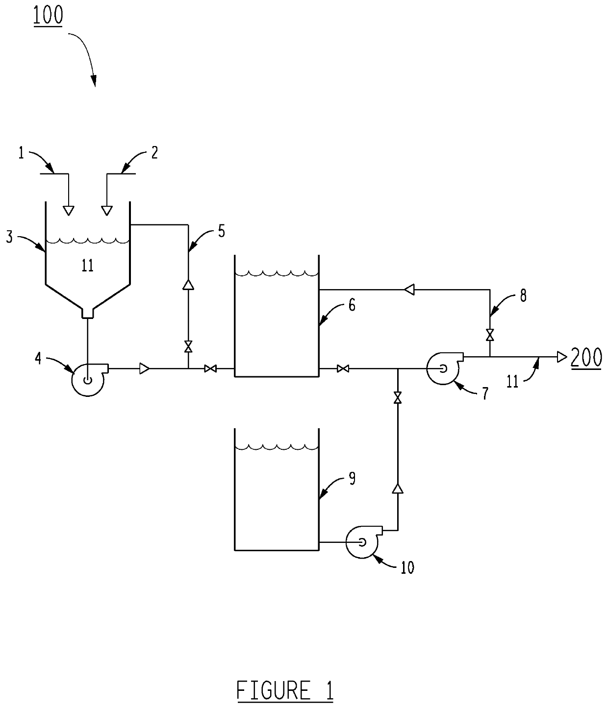
[0019]FIG. 1 shows urea solution system (100), comprising a urea solution mix tank (3), urea prill (1) and condensate (2) from condensate tank (9). This preferred embodiment does not necessitate a mixer but the use of mixers would suffice. A mix tank pump (4) pumps the resulting urea solution (11) to a urea solution tank (6) and ultimately to direct injection system (200). The concentration of the urea solution (11) in this preferred embodiment is 32.5%.

[0020]A recirculation line (5) and mix tank pump (4) aid with mixing of the urea solution (11) in urea solution mix tank (3). A flushing pump (10) is preferred to flush out system (100). A urea solution pump (7) supplies urea solution (11) to system (200). A urea solution recirculation line (8) protects the urea solution pump (7).

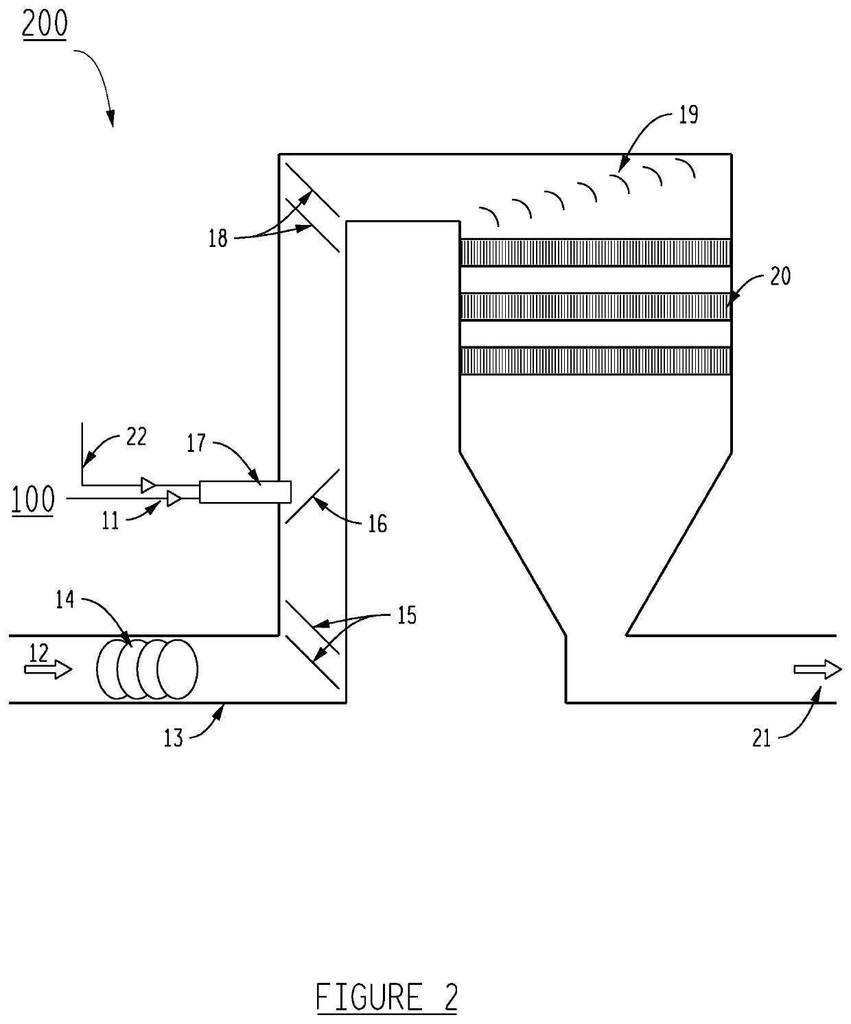
[0021]FIG. 2 shows the urea solution (11) injected into flue gas (12) in flue gas duct (13) of direct injection system (200). Direct injection system (200) comprises a solid fuel combustion unit, which in th...


PUM

PropertyMeasurementUnit
concentrationaaaaaaaaaa
pressureaaaaaaaaaa
temperatureaaaaaaaaaa

Abstract

This disclosure provides an apparatus and method for reducing emissions of nitrogen oxides (NOx) from a combustion source. For example, a method and apparatus for injecting a urea solution directly into the flue gas stream of a coal-fired power plant that utilizes Selective Catalytic Reduction (SCR) to lower NOx emissions.

Description

BACKGROUND OF THE INVENTION1. Field of the Invention[0001]The present disclosure relates generally to a method and apparatus for reducing emissions of nitrogen oxides (NOx) from a combustion source. More particularly, to injecting a urea solution directly into the flue gas stream of a coal-fired power plant that utilizes Selective Catalytic Reduction (SCR) to lower NOx emissions. This invention herein eliminates the vast equipment, risks of using anhydrous ammonia, and costs associated with using aqueous ammonia, or complicated systems to hydrolyze urea, before injection.2. Description of the Related Art[0002]One process for lowering NOx emissions is SCR, which involves chemically converting NOx to elemental nitrogen by injecting a reagent, often anhydrous ammonia, aqueous ammonia, or aqueous urea.[0003]The following equations describe SCR with urea as the reagent:(NH2)2CO+H2O→2NH3+CO2  Eq. 1:2NO+2NH3+½O2→2N2+3H2O and  Eq. 2:3NO2+4NH3→3½N2+6H2O  Eq. 3:[0004]The prior art contains va...

Claims


Application Information

Patent Timeline
Patent Type & Authority Patents(United States)
IPC IPC(8): B01D53/90B01D53/86
CPCB01D53/90B01D53/8631B01D2251/2067B01D2258/0291B01D53/8625B01D2258/0283
Inventor HANBY, DARREN CHOFACRE, JEFFERY L
Owner AMERICAN ELECTRIC POWER CO INC
Why Eureka
Try Eureka