
Self-calibrating position determination system

a self-calibrating and position determination technology, applied in the direction of mechanical measuring arrangements, instruments, mechanical means, etc., can solve the problems of consuming time, troublesome removal and reinstallation of aligners, and inability to resolve problems,

Inactive Publication Date: 2005-01-11
SNAP ON INC
View PDF28 Cites 31 Cited by
  • Summary
  • Abstract
  • Description
  • Claims
  • Application Information

AI Technical Summary

Problems solved by technology

These approaches, however, do not resolve a problem encountered by position determination systems.
The removal and reinstallation of the aligner is troublesome and consumes time.
In addition, after the aligner is reinstalled, it takes time to aim the cameras towards the alignment targets.

Method used


Image

  • Self-calibrating position determination system
  • Self-calibrating position determination system
  • Self-calibrating position determination system

Examples


Embodiment Construction

In the following description, for the purposes of explanation, numerous specific details are set forth in order to provide a thorough understanding of the present disclosure. It will be apparent, however, to one skilled in the art that the present disclosure may be practiced without these specific details. In other instances, well-known structures and devices are shown in block diagram form in order to avoid unnecessarily obscuring the present disclosure.

System Overview

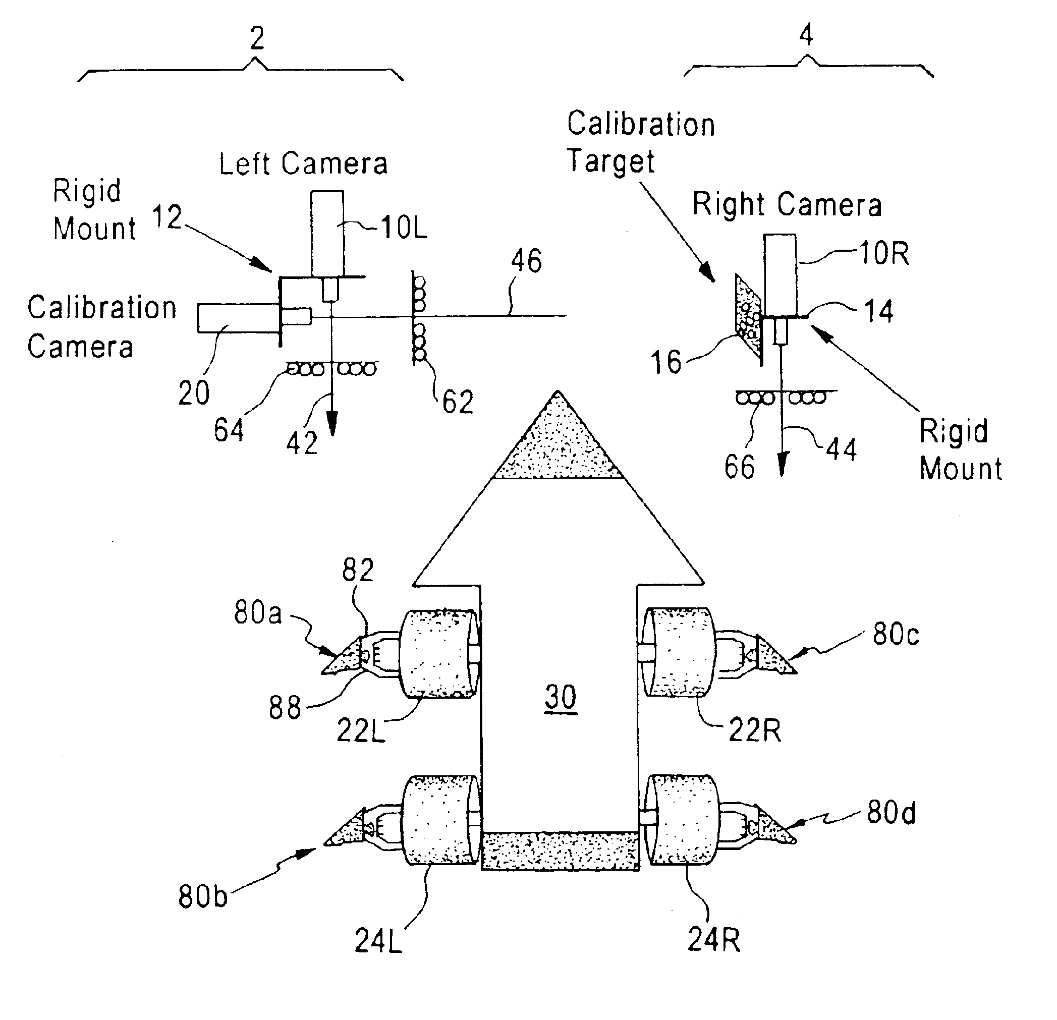
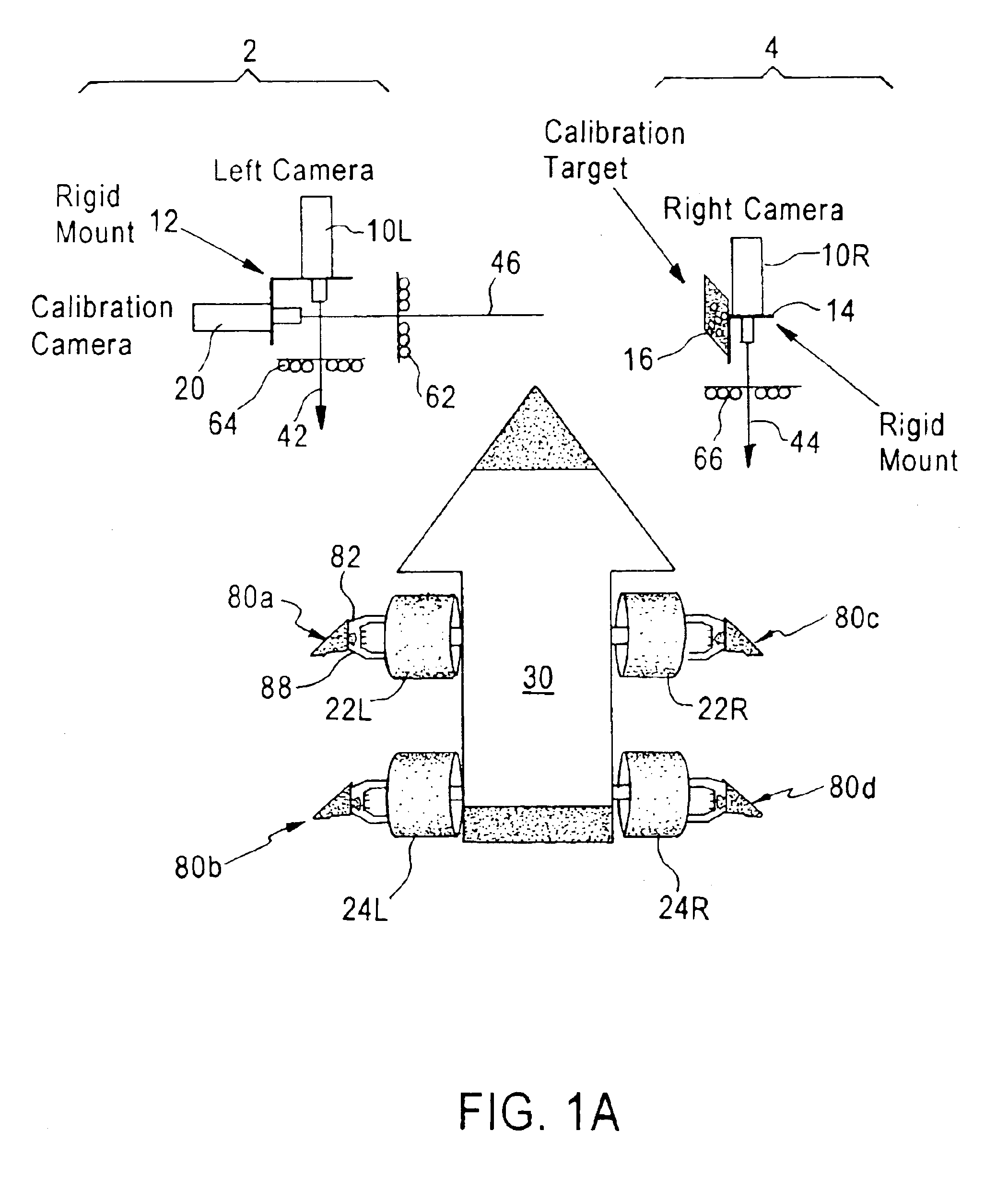
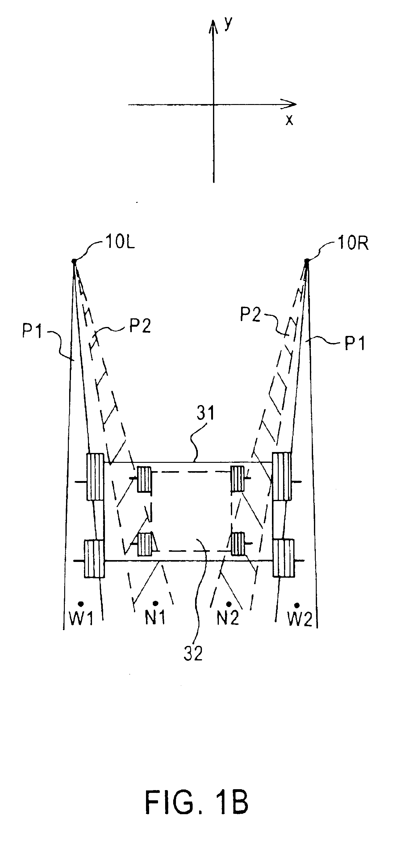
A computer-aided wheel alignment system (“aligner”) upon which an exemplary position determination system may be implemented is described. The aligner includes alignment cameras for capturing images and generating positional data of alignment targets affixed to a vehicle under test, a data processing system for processing the positional data and determining the positions of the alignment targets, and a repositioning mechanism configured to reposition the viewing fields of the alignment cameras. Depending on the size o...


PUM


Abstract

A position determination system comprises a first measuring apparatus and a second measuring apparatus. The first measuring apparatus includes a first sensing device having a sensing field for obtaining positional data of a first testing target, a calibration target rigidly linked to the first sensing device, wherein the positional relationship between the first sensing device and the calibration target is known. The system has a repositioning mechanism for repositioning the sensing field of the first sensing device. The second measuring apparatus includes a second sensing device having a sensing field for obtaining positional data of a second testing target, a calibration sensing device rigidly linked to the second sensing device for obtaining positional data of the calibration target, wherein the positional relationship between the second sensing device and the calibration sensing device is known, and a repositioning mechanism for repositioning the sensing field of the second sensing device. Depending on different needs, the repositioning mechanism readjust the viewing fields of the sensing devices such that the testing targets are properly within the sensing fields of the sensing devices.

Description

FIELD OF THE DISCLOSUREThe disclosure generally relates to a position determination method and system, and more specifically, to a method and system for adjusting a self-calibrating position determination system to adapt to different needs.BACKGROUND OF THE DISCLOSUREPosition determination systems, such as a machine vision measuring system, are used in many applications. For example, wheels of motor vehicles may be aligned using a computer-aided, three-dimensional machine vision alignment apparatus and a related alignment method. Examples of 3D alignment are described in U.S. Pat. No. 5,724,743, titled “Method and apparatus for determining the alignment of motor vehicle wheels,” and U.S. Pat. No. 5,535,522, titled “Method and apparatus for determining the alignment of motor vehicle wheels,” both of which are commonly assigned to the assignee of the present disclosure and incorporated herein for reference.To determine the alignment status of the vehicle wheels, some aligners use dire...

Claims


Application Information

Patent Timeline
Patent Type & Authority Patents(United States)
IPC IPC(8): G01C11/06G01B11/00G01B11/275G01C11/00H04N13/00H04N13/239
CPCG01B11/002G01B11/2755G01C11/06H04N13/0246H04N13/0239H04N2013/0081H04N13/0242H04N13/243H04N13/246H04N13/239
Inventor JACKSON, DAVID A.BLIVEN, BRIAN M.O'MAHONY, PATRICK B.
Owner SNAP ON INC
Learn More