
Heating oven for dynamo-electric machine component manufacture

a technology of dynamo-electric machines and components, which is applied in the direction of heating apparatus, fluid friction for heating, furnaces, etc., can solve the problems of mechanical wound wires, generating electromechanical forces that tend to loosen or deform the shape of wire coils, and generating vibration and heat. , to achieve the effect of streamlining air flow and minimizing or reducing air flow dead spaces

Inactive Publication Date: 2005-01-11
AXIS USA
View PDF62 Cites 5 Cited by
  • Summary
  • Abstract
  • Description
  • Claims
  • Application Information

AI Technical Summary

Benefits of technology

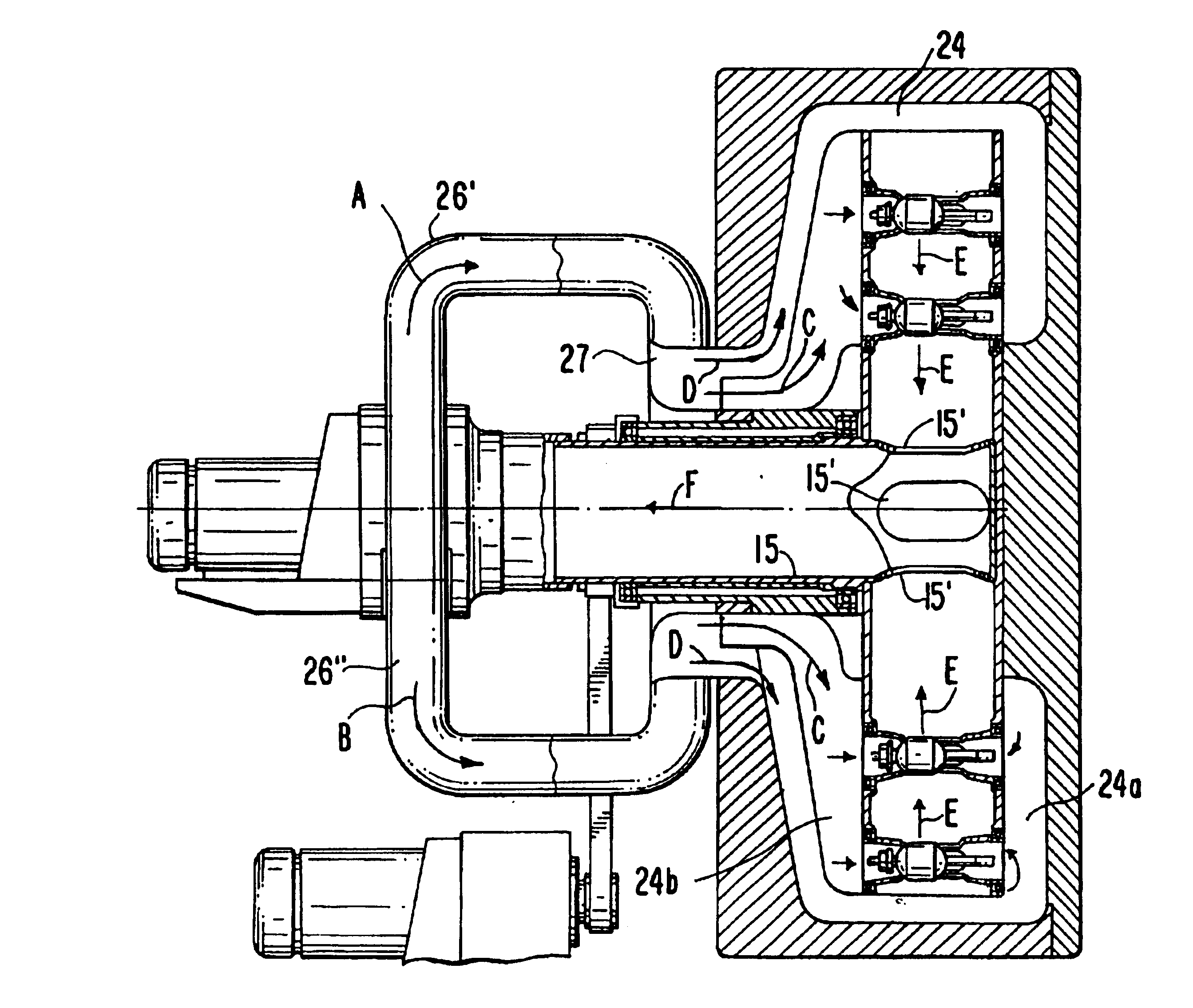
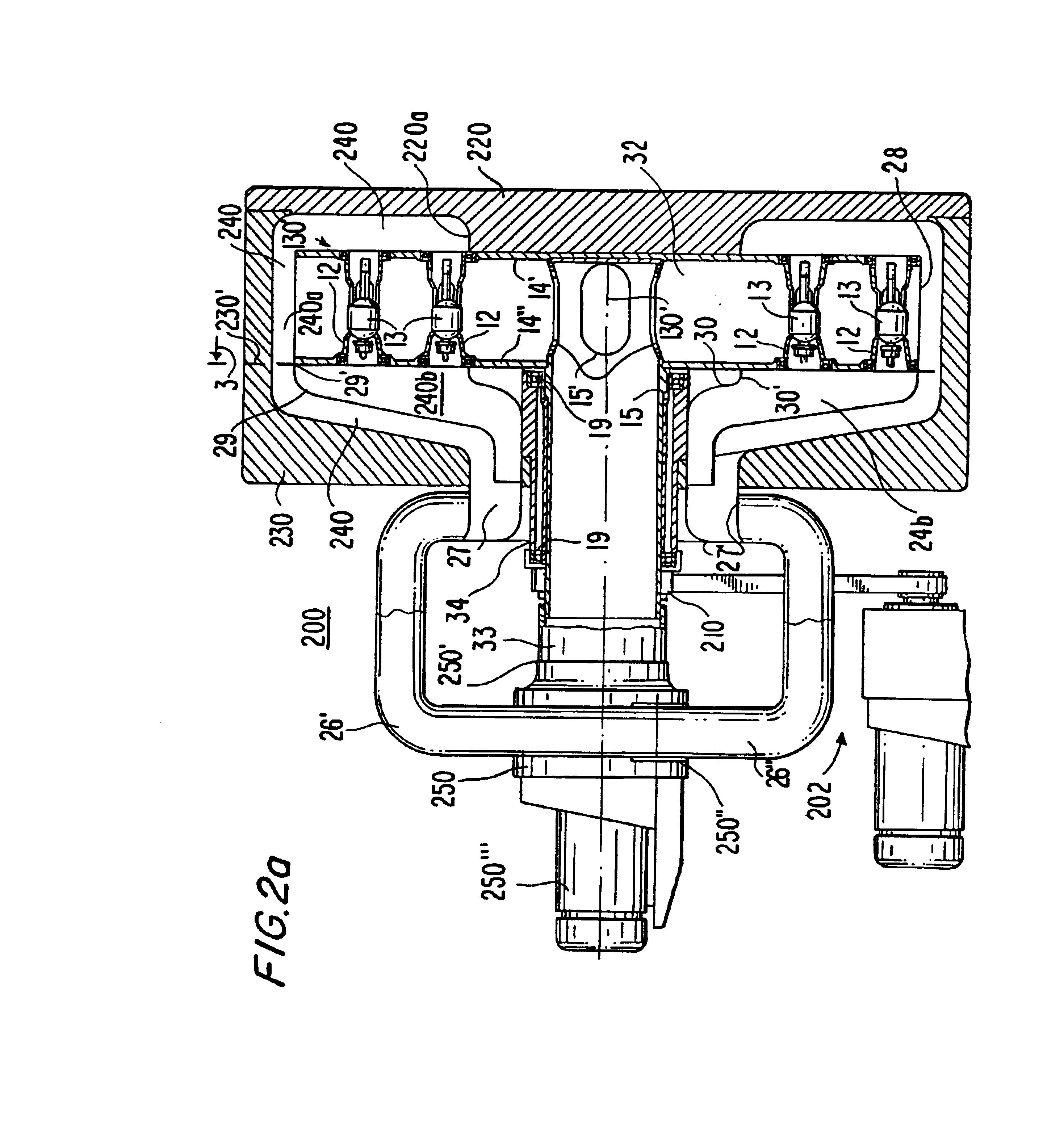
Input air flow paths or channels are set up in the oven cabinet using, for example, baffles, to evenly distribute and direct freshly heated air along or over each individual subassembly loaded in the oven cabinet. Further a common air-distribution manifold may be used to evenly or symmetrically feed heated air into the oven cabinet for flow along the paths or channels leading to the individual in-process subassemblies.
Additional baffles or other mechanical structures may be used to streamline the air flow by minimizing or reducing air flow dead spaces in the oven cabinet.

Problems solved by technology

However, the wires in the coils, which are mechanically wound, are susceptible to loosening due to vibration or heat during further manufacturing or assembly steps.
Operation of the dynamo-electric machine itself also may cause vibrations and heat, which tend to loosen the wire coils.
Electrical current, which passes through the wire coils, also may generate electromechanical forces that tend to loosen or deform the wire coil shapes.
Non-uniform temperatures across the impregnated resin on a dynamo-electric machine component may adversely affect the quality the hardened resin coating.
Further, component-to-component differences or variations in heating may adversely affect manufacturing process uniformity and reproducibility, which are desirable for commercial production.

Method used


Image

  • Heating oven for dynamo-electric machine component manufacture
  • Heating oven for dynamo-electric machine component manufacture
  • Heating oven for dynamo-electric machine component manufacture

Examples


Embodiment Construction

The present disclosure provides solutions for uniform and reproducible manufacturing of dynamo-electric machine components. A disclosed solution concerns heating furnaces or ovens, which may be used for heating batches of dynamo-electric machine component subassemblies, which have wire coil portions, to elevated processing temperatures.

The disclosed solution may find application in dynamo-electric machine component manufacturing processes where inter- or intra-component processing temperature uniformity is an important process parameter. The disclosed heating furnaces or ovens may be used, for example, as ovens to preheat dynamo-electric machine component subassemblies in preparation for resin application, or as resin-curing ovens. The furnaces or ovens may be integrated into a manufacturing assembly line by the use of suitable conveyor apparatus and component transfer devices. The conveyor apparatus may, for example, carry the component subassemblies in pallets placed on belts runn...


PUM


Abstract

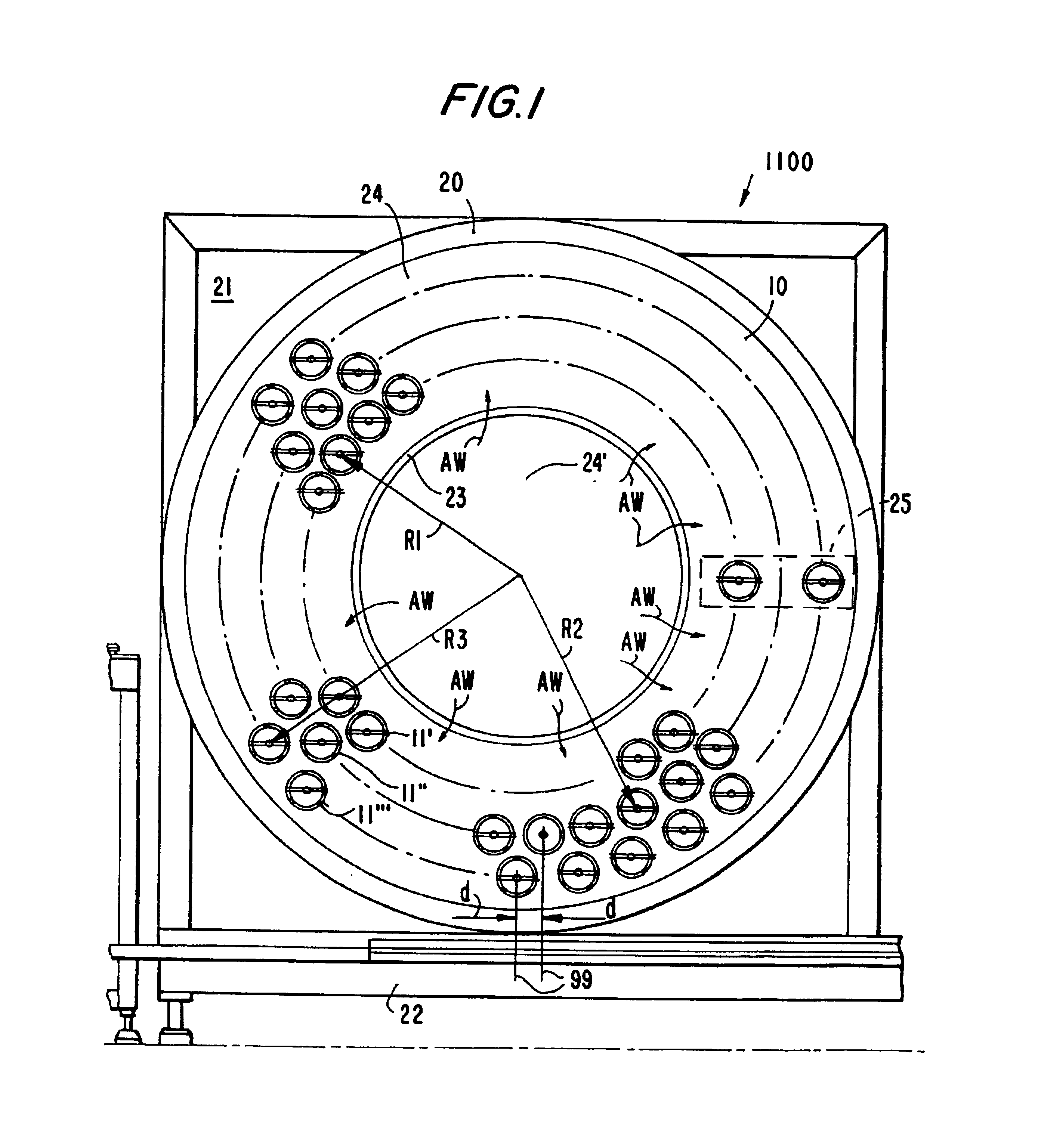
A heating oven for use in dynamo-electric machine component manufacture is provided. The oven uses forced air heating to raise the temperature of in-process component subassemblies to suitable process temperatures. The heating oven includes a rotating drum mounted in a cabinet. A number of open-ended tubular cradles are disposed in circular arrays between the drum faces. Batches of component subassemblies may be individually loaded into the cradles for heat treatment. Air flow channels are set up in the oven cabinet to evenly distribute heated air through individual cradles. Heated air after passing over the individual in-process subassemblies, exits the cradles through side slots in the cradle walls into the interior of the drum. The exiting air is reheated and recirculated through the heating oven.

Description

BACKGROUND OF THE INVENTIONThe present invention relates to improved solutions for processing dynamo-electric machine components (e.g., armatures or stators for electric motors, generators, or alternators) through resin application process steps.Resin application steps are common in the manufacturing of dynamo-electric machine components. The dynamo-electric machine components such as armatures include insulated wire coils wound on ferromagnetic cores. Electric current passes through the wire coils in the operation of the dynamo-electric machine in which the component is used. For optimal performance of the dynamo, the dynamo-electric machine components' wire coils may be subject to tight dimensional tolerances. However, the wires in the coils, which are mechanically wound, are susceptible to loosening due to vibration or heat during further manufacturing or assembly steps. Operation of the dynamo-electric machine itself also may cause vibrations and heat, which tend to loosen the w...

Claims


Application Information

Patent Timeline
IPC IPC(8): F24J3/00F26B11/02F26B11/04F26B11/00H02K15/12
CPCF24J3/003H02K15/12F26B11/04F26B11/028F24V40/00
Inventor BECHERUCCI, RAFFAELESTRATICO, GIANFRANCO
Owner AXIS USA
Learn More