Connector

a technology of connecting rods and connectors, applied in the direction of coupling devices, two-part coupling devices, electrical equipment, etc., can solve the problems of cable workers bending, the direction in which flat cables can be routed or bent, etc., and achieve the effect of preventing the breaking of flat cables

Inactive Publication Date: 2005-01-11
JAPAN AVIATION ELECTRONICS IND LTD
View PDF8 Cites 49 Cited by
  • Summary
  • Abstract
  • Description
  • Claims
  • Application Information

AI Technical Summary

Benefits of technology

It is an object of the present invention to provide a connector that permits a flat cable to be r...

Problems solved by technology

Therefore, when the connector is fitted to a mating connector fixed to a casing, a direction in which the flat cable can be routed or bent is limited to the direction of thickness ...

Method used


Image

  • Connector
  • Connector
  • Connector

Examples


second embodiment

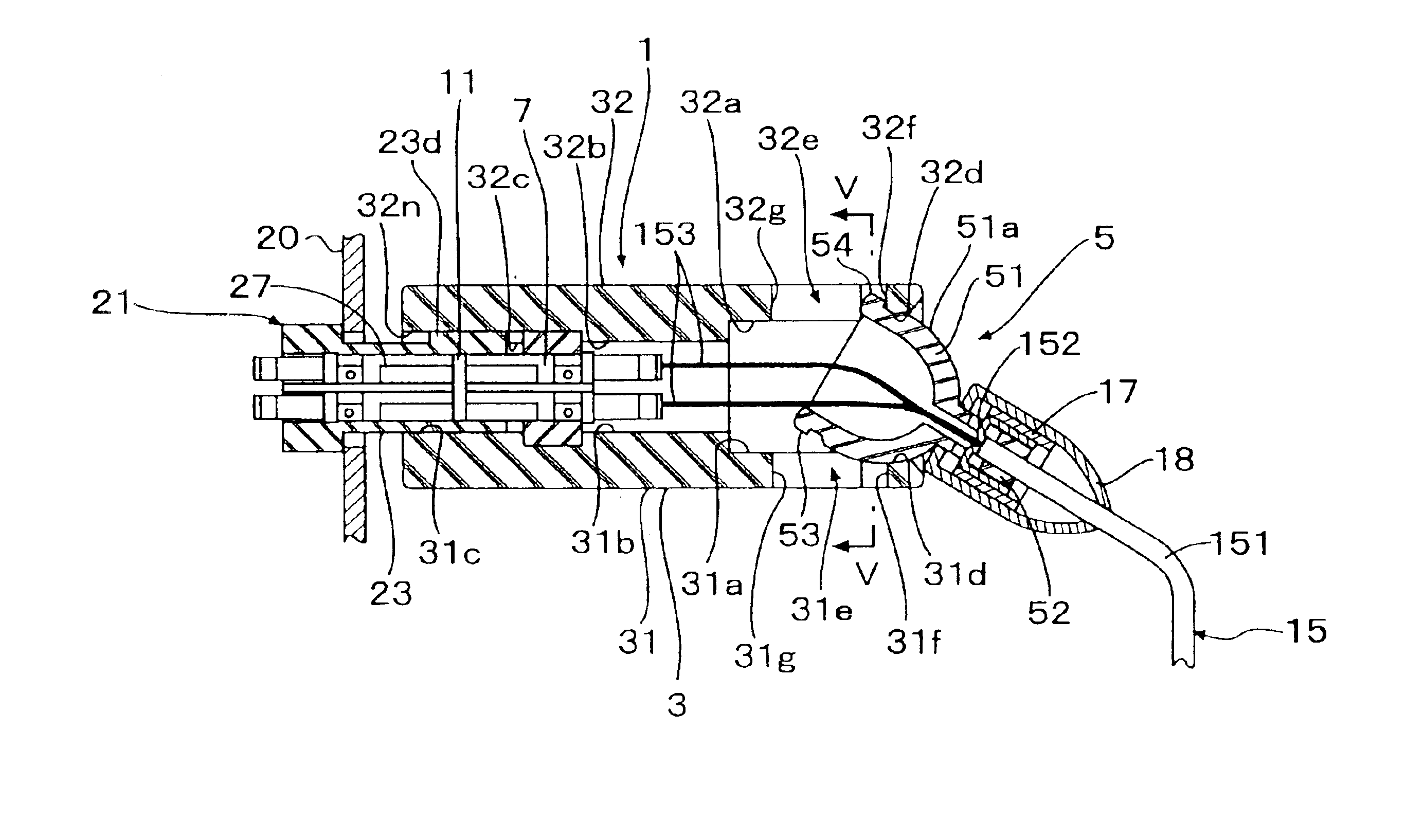
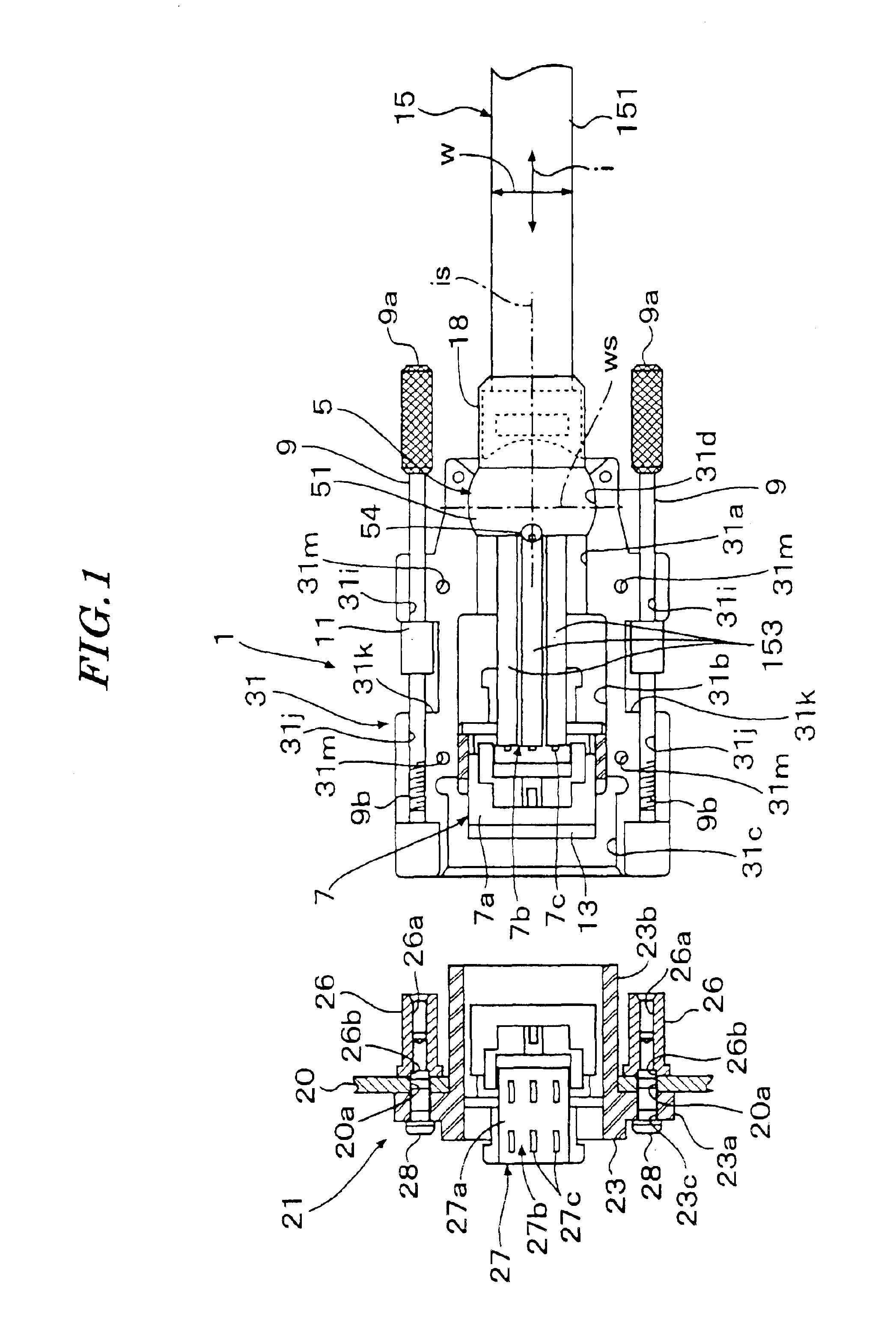
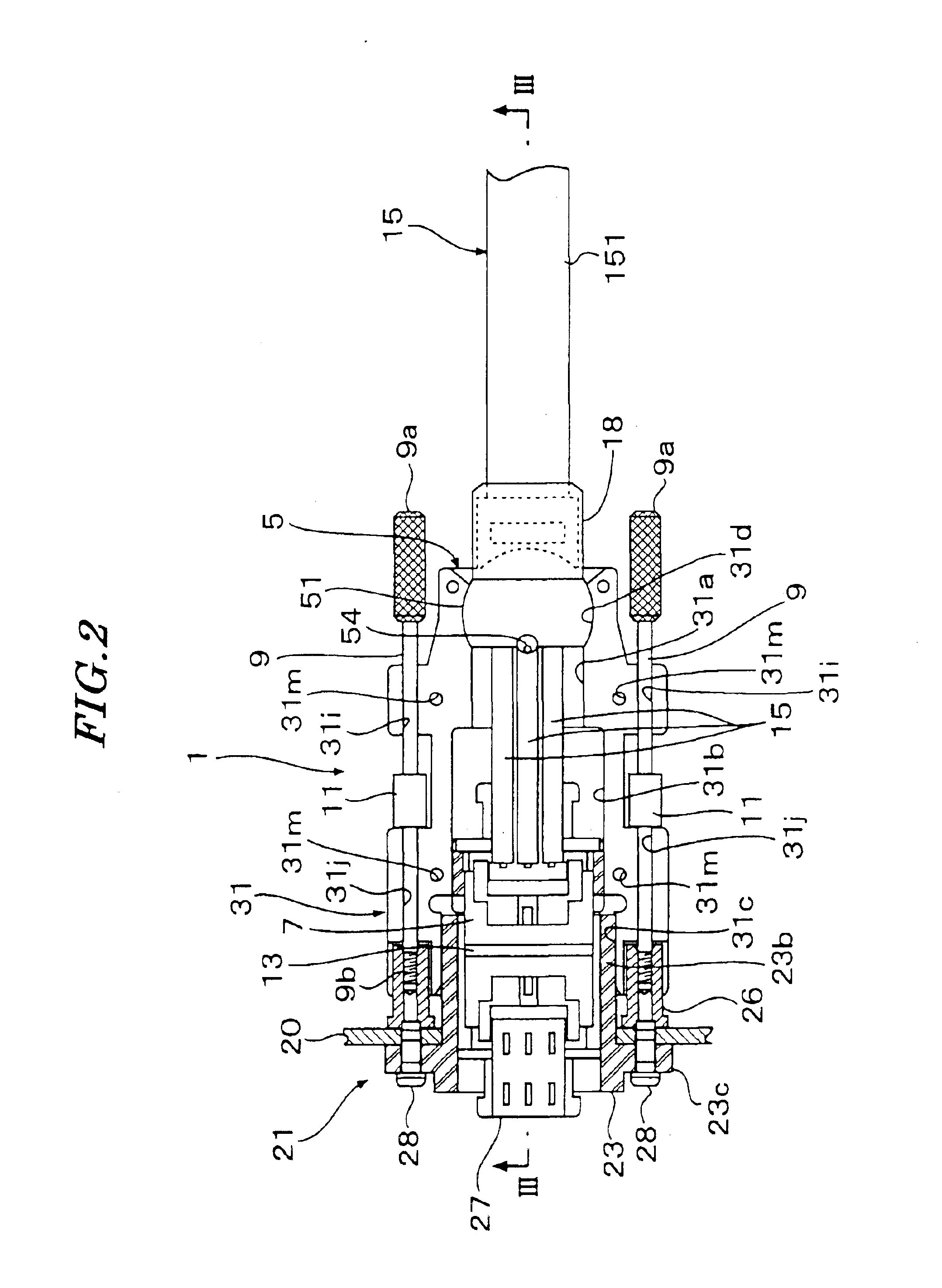
FIG. 8 is a longitudinal cross-sectional view of an optical connector according to the invention in a connected state with a flat cable extending straight, and FIG. 9 is a longitudinal cross-sectional view of the FIG. 8 optical connector, with the flat cable bent.

Although in the first embodiment, the cable-holding member 5 has the two projections 53, 54 formed thereon, in the present embodiment, a cable-holding member 205 has only one projection 254 formed thereon. Further, the cable-holding member 205 has no projection at a lower portion thereof, as viewed in FIG. 8, and accordingly, a concave portion 231d of a lower housing member 231 has no slit formed therein.

According to the second embodiment, rotation-restricting means is simplified in construction to facilitate the machining of the cable-holding member 205 and the lower housing member 231, which contributes to reduction of manufacturing costs of the optical connector.

Although in the first embodiment, there are arranged two pr...


PUM


Abstract

There is provided a connector which is capable of routing a flat cable in a desired arbitrary direction and at the same time preventing the flat cable from being broken. A concave portion is formed in a housing, and a convex portion is formed on a cable-holding member for being slidably fitted in the concave portion. Slits are formed in the concave portion, and projections to be engaged with the slits are formed on the cable-holding member. Thus, directions of rotations of the cable-holding member are restricted such that the cable-holding member can rotate only about a first axis extending in a direction of width of the flat cable and a second axis orthogonal to the first axis and extending in a direction of insertion of the flat cable.

Description

BACKGROUND OF THE INVENTION1. Field of the InventionThis invention relates to a connector for a so-called flat cable having a plurality of conductor wires or optical fibers arranged therein in parallel with each other and covered with sheathing.2. Prior ArtA conventional connector for a flat cable includes a housing and a cable-holding member. One end of the flat cable is inserted into the housing. The cable-holding member is fixed to the housing with the flat cable held therein.On the other hand, there is a connector for a cable other than the flat cable, which has a cable-holding member rotatable with respect to a housing (see e.g. Publication of Utility Model Registration No. 2512513). An end of a cable inserted into the housing is held by the cable-holding member, and the cable-holding member is rollably held by the housing.The flat cable can be bent in the direction of thickness thereof, but not in the direction of width thereof. As described above, in the conventional connecto...

Claims


Application Information

Patent Timeline
IPC IPC(8): H01R12/24H01R13/00H01R12/00H01R13/56H01R13/621
CPCH01R13/562H01R23/661H01R13/6215H01R12/772
Inventor TAKEDA, JUNKOREEDA, YUICHI
Owner JAPAN AVIATION ELECTRONICS IND LTD
Why Eureka
Try Eureka