Reflection projection screen

a projection screen and projection screen technology, applied in the field of front projection screens, can solve the problems of eye pain, image cannot be clearly displayed,

Inactive Publication Date: 2005-01-11
ARISAWA MFG CO LTD
View PDF12 Cites 69 Cited by
  • Summary
  • Abstract
  • Description
  • Claims
  • Application Information

AI Technical Summary

Problems solved by technology

When an image is projected on such a screen by a projector in a well-lighted room, the image cannot be displayed clearly due to the reduction of contrast or the loss of color balance.
When images are projected on a high-luminance bead screen by a high-luminance projector, a person is made to feel pains in the eyes by the glare of beads due to light regression when the person watches images displayed on the high-luminance bead screen for a long time.

Method used


Image

  • Reflection projection screen
  • Reflection projection screen
  • Reflection projection screen

Examples


first embodiment

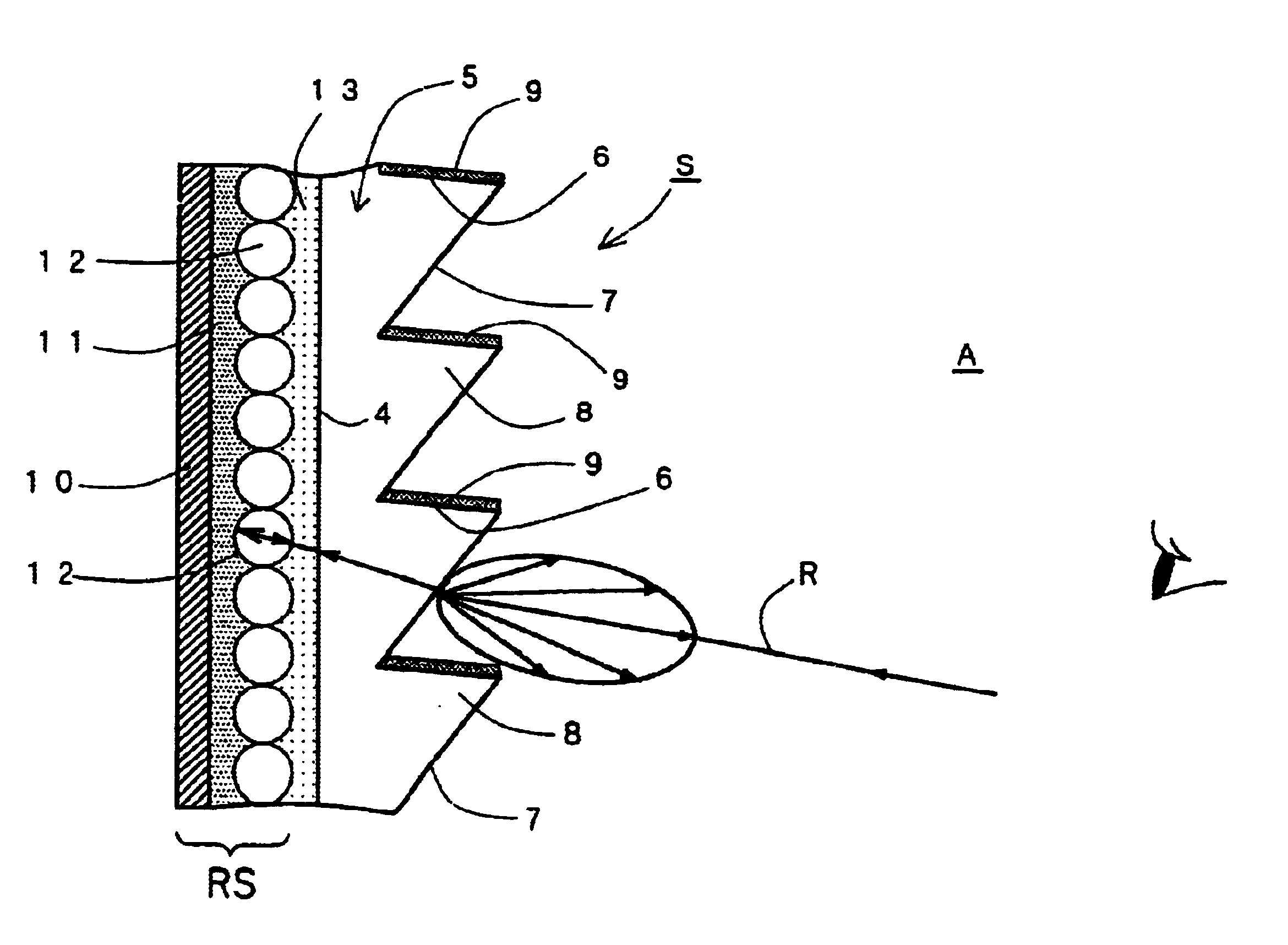
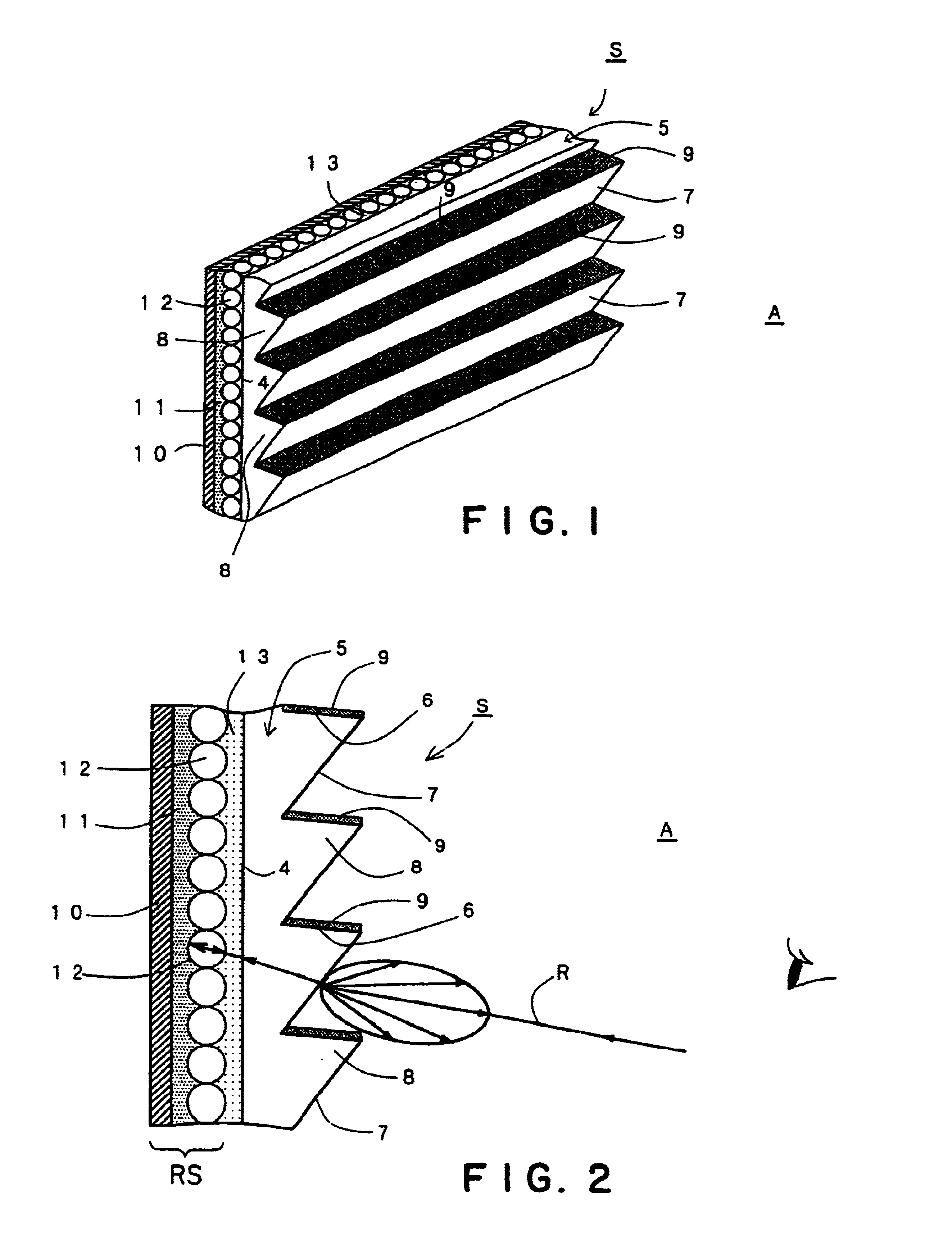
FIG. 1 is a perspective view of a front projection screen in a first embodiment according to the present invention, and FIG. 2 is a longitudinal sectional view of the front projection screen shown in FIG. 1.

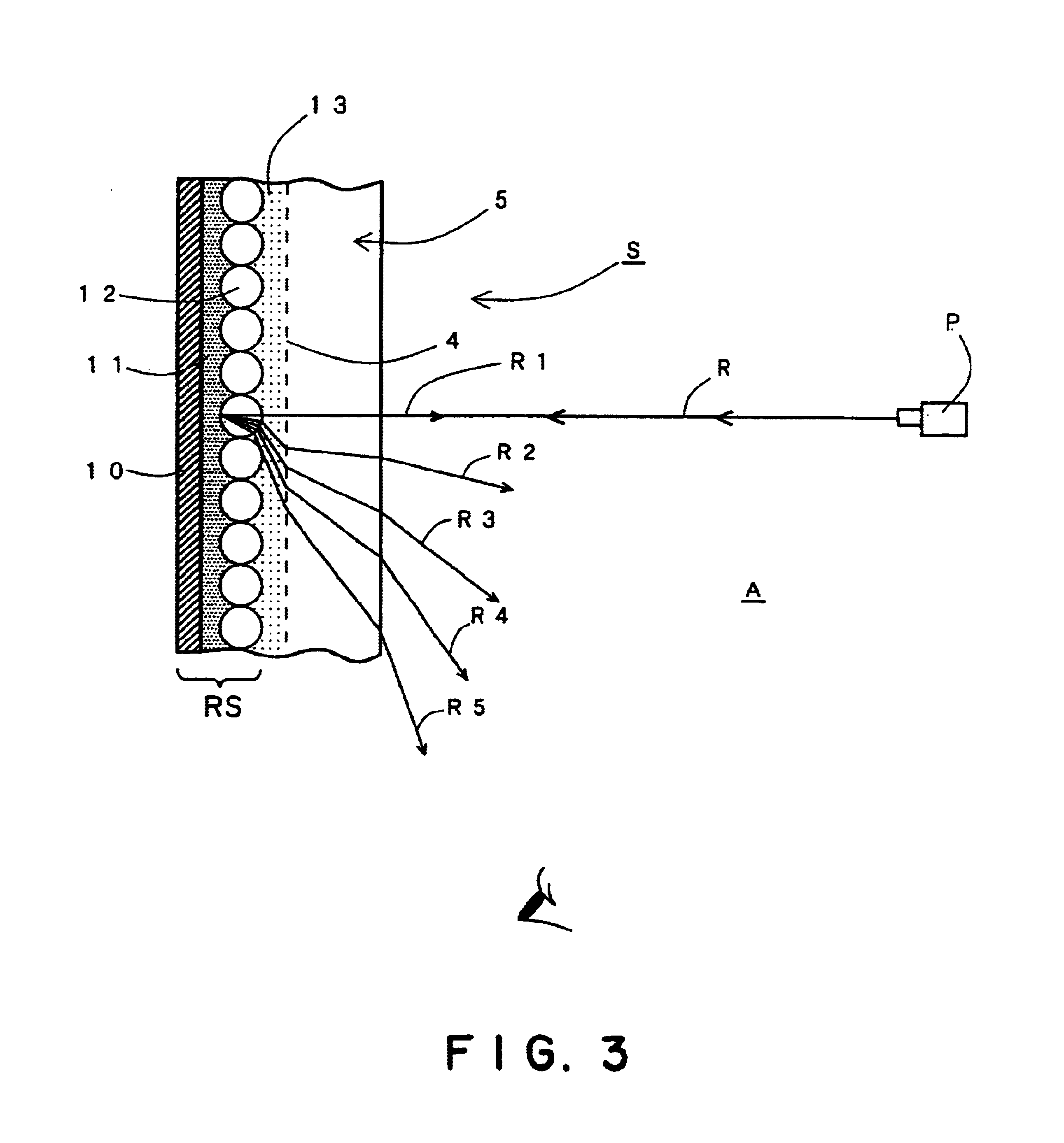
The front projection screen in the first embodiment is a front projection screen of a light regression type that reflects projected imaging light so that the reflected imaging light travels in a direction opposite to the direction of travel of the projected imaging light. The reflected imaging light is caused to travel in a direction opposite to the direction of travel of the projected imaging light by the reflecting function of transparent glass beads 12, which will be described later.

As shown in FIGS. 1 and 2, a front projection screen S in a first embodiment according to the present invention has a front shading sheet 5 wholly formed of a transparent material and facing a viewing side A. The front shading sheet 5 is formed of a transparent, flexible synthetic resin, such as a ...

third embodiment

Referring to FIG. 8, a front projection screen S in a third embodiment according to the present invention is formed in a flexible sheet and is wound on a vertical take-up spool 52. The front projection screen S is rolled out by pulling the same laterally. A long, flexible shape-retaining member 53 is attached to the upper edge of the front projection screen S for shape retention.

fourth embodiment

Referring to FIG. 9, a front projection screen S in a fourth embodiment according to the present invention is formed in a rectangular, flexible sheet and is set in a rectangular frame 54. The front projection screen S is tensioned by a plurality of connecting members 55. The connecting members 55 may be connected to grommets or the like attached to the front projection screen S. In FIG. 9, the front projection screen S and the frame 54 are curved in a cylindrical shape.

The front projection sheet S does not necessarily need to be a flexible sheet, but may be a hard structure capable of shape retention.


PUM


Abstract

A front projection screen (S) has a front shading sheet (5) facing a viewing side (A), and formed of a transparent material. The front shading sheet (5) has a front surface facing the viewing side (A), provided with a plurality of horizontal, parallel, minute ridges (8) having a triangular cross section and each having an upper side surface coated with a shading layer (9). A transparent filler layer (13) of a material having a refractive index nearly equal to that of the transparent material of the front shading sheet (5) is formed on the rear surface (4) of the front shading sheet (5), transparent glass beads (12) are embedded uniformly in a plane in the rear surface of the transparent filler layer (13), the rear surface of the transparent filler layer (13) is coated with a white, reflecting adhesive layer (11), and an opaque film (10) impermeable to light is applied to the rear surface of the reflecting adhesive layer (11). Horizontal end parts of an image displayed on the front projection screen (S) do not become dark, the front projection screen (S) has a large viewing angle, does not reflect an environmental image even in a light environment, and is capable of displaying a high-definition image having a high black level and a high contrast.

Description

TECHNICAL FIELDThe present invention relates to a front projection screen that displays a image projected by an image-projecting device, such as a slide projector, a liquid crystal projector or a moving picture projector.BACKGROUND ARTFront projection screens for displaying images projected by a projector include white matrix screens, chemical etching screens, and high-luminance bead screens. When an image is projected on such a screen by a projector in a well-lighted room, the image cannot be displayed clearly due to the reduction of contrast or the loss of color balance. Therefore, room lights of the room must be turned off to darken the room. When images are projected on a high-luminance bead screen by a high-luminance projector, a person is made to feel pains in the eyes by the glare of beads due to light regression when the person watches images displayed on the high-luminance bead screen for a long time. The term “light regression” signifies return of imaging light in a direct...

Claims


Application Information

Patent Timeline
Patent Type & Authority Patents(United States)
IPC IPC(8): G03B21/60
CPCG03B21/602G03B21/60G02B5/0284G02B5/0226E06B9/42
Inventor KURODA, KAZUMITANAKA, KOJIWAKABAYASHI, YOSHIOFUKUDA, TATSUFUMI
Owner ARISAWA MFG CO LTD
Why Eureka
Try Eureka