Supply independent low quiescent current undervoltage lockout circuit

a low quiescent current and lockout circuit technology, applied in the field of electronic systems, can solve problems such as current through the resistor divider

Inactive Publication Date: 2005-01-11
TEXAS INSTR INC
View PDF12 Cites 16 Cited by
  • Summary
  • Abstract
  • Description
  • Claims
  • Application Information

AI Technical Summary

Problems solved by technology

The problems associated with this circuit is the current through the resistor divider 14 is a function of input voltage and generally quite large.

Method used


Image

  • Supply independent low quiescent current undervoltage lockout circuit
  • Supply independent low quiescent current undervoltage lockout circuit
  • Supply independent low quiescent current undervoltage lockout circuit

Examples


Embodiment Construction

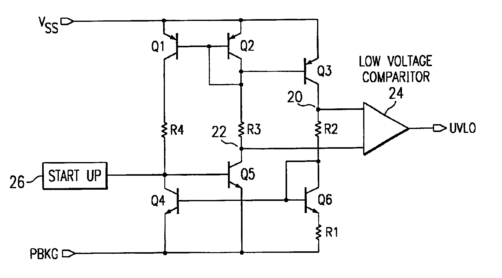
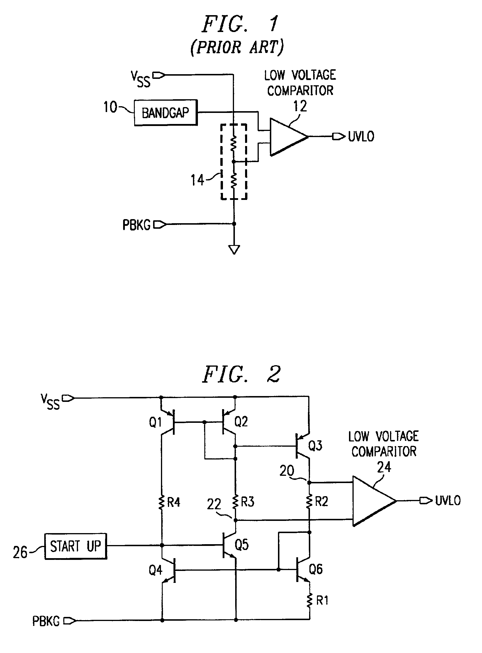
A preferred embodiment undervoltage (UVLO) circuit is shown in FIG. 2. The circuit of FIG. 2 provides an accurate UVLO circuit that has a very low quiescent current that is independent of supply voltage. It is also a very small circuit that has a minimum number of active components and a low amount of resistance to minimize its area.

In the preferred embodiment circuit of FIG. 2, transistors Q1-Q6 and resistor R1 make a standard low voltage IPTAT (current proportional to absolute temperature) generator. By adding resistor R2 in series with transistor Q6, a bandgap voltage is formed at node 20 with respect to ground PBKG. Adding resistor R3 in series with transistor Q2 forms a bandgap voltage with respect to the supply VSS. The voltage at nodes 20 and 22, with respect to ground, will be equal when the input voltage VSS is equal to two bandgap voltages. By using a low voltage comparator 24 that is biased off the IPTAT generator, a UVLO signal will be generated.

Resistor R4 is optional, ...


PUM


Abstract

The UVLO (undervoltage lockout) circuit provides a very low quiescent current that is independent of supply voltage. The circuit includes a low voltage IPTAT (current proportional to absolute temperature) generator coupled to a comparator 24 wherein a first input of the comparator 24 is coupled to the IPTAT generator in a way that forms a bandgap voltage with respect to ground and a second input of the comparator 24 is coupled to the IPTAT generator in a way that forms a bandgap voltage with respect to a supply node. This makes the quiescent current independent of the supply voltage because there is no voltage divider between the supply node and ground.

Description

FIELD OF THE INVENTIONThis invention generally relates to electronic systems and in particular it relates to undervoltage lockout circuits.BACKGROUND OF THE INVENTIONA prior art undervoltage lockout circuit is shown in FIG. 1. This circuit consists of a low voltage bandgap 10, a low voltage comparator (i.e., comparator) 12, and resistor divider 14 from the input voltage VSS to ground PBKG. The problems associated with this circuit is the current through the resistor divider 14 is a function of input voltage and generally quite large.SUMMARY OF THE INVENTIONA UVLO (undervoltage lockout) circuit provides a very low quiescent current that is independent of supply voltage. The circuit includes a low voltage IPTAT (current proportional to absolute temperature) generator coupled to a comparator wherein a first input of the comparator is coupled to the IPTAT generator in a way that forms a bandgap voltage with respect to ground and a second input of the comparator is coupled to the TPTAT g...

Claims


Application Information

Patent Timeline
Patent Type & Authority Patents(United States)
IPC IPC(8): H02H3/24
CPCH02H3/243
Inventor BROHLIN, PAUL L.
Owner TEXAS INSTR INC
Why Eureka
Try Eureka