Method for automatic device monitoring by a central computer

a technology of automatic device monitoring and central computer, which is applied in the direction of program control, testing/monitoring control system, instruments, etc., can solve the problems of inability to adjust the nature of data transmission between central computer and connector devices without user intervention

Inactive Publication Date: 2005-01-11
INTEL CORP
View PDF19 Cites 55 Cited by
  • Summary
  • Abstract
  • Description
  • Claims
  • Application Information

AI Technical Summary

Problems solved by technology

Prior systems such as system 300 possess a disadvantage in that they are incapable of adjusting the nature of data transmissions between central computer 306 and connector devices without user intervention.

Method used


Image

  • Method for automatic device monitoring by a central computer
  • Method for automatic device monitoring by a central computer
  • Method for automatic device monitoring by a central computer

Examples


Embodiment Construction

A computer implemented method for monitoring and controlling a plurality of devices in a common environment will be described. The method includes automatically communicating with devices and automatically connecting to a remote database at specified intervals to collect information regarding specific devices. The information regarding specific devices is automatically processed and used to generate reports regarding maintenance of the device and also to alter the nature or frequency of commands transmitted to a device from a central controller.

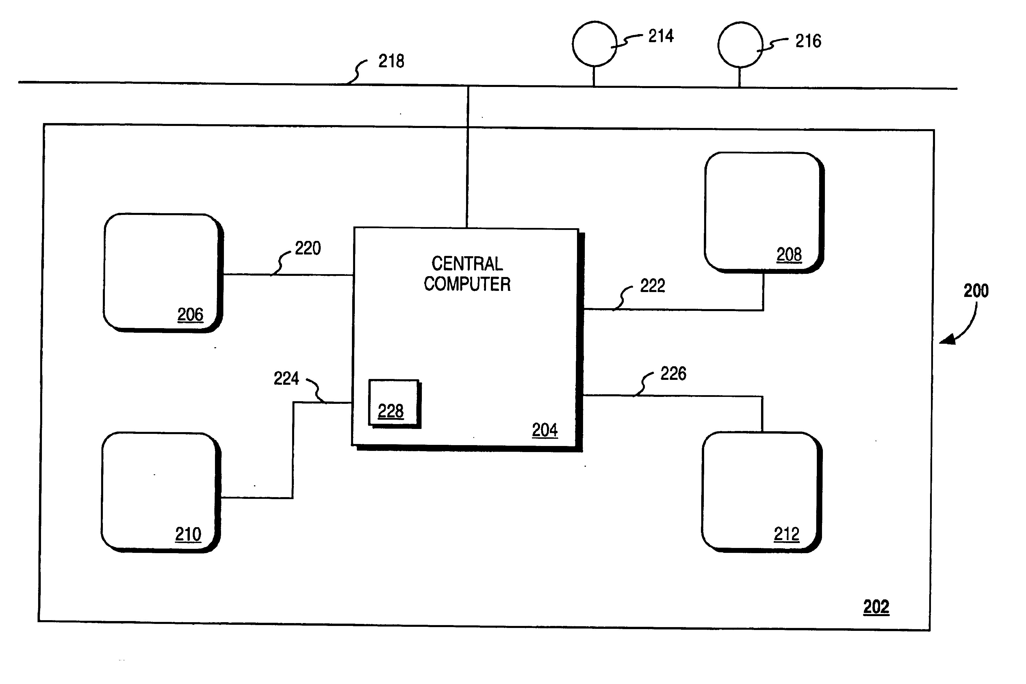
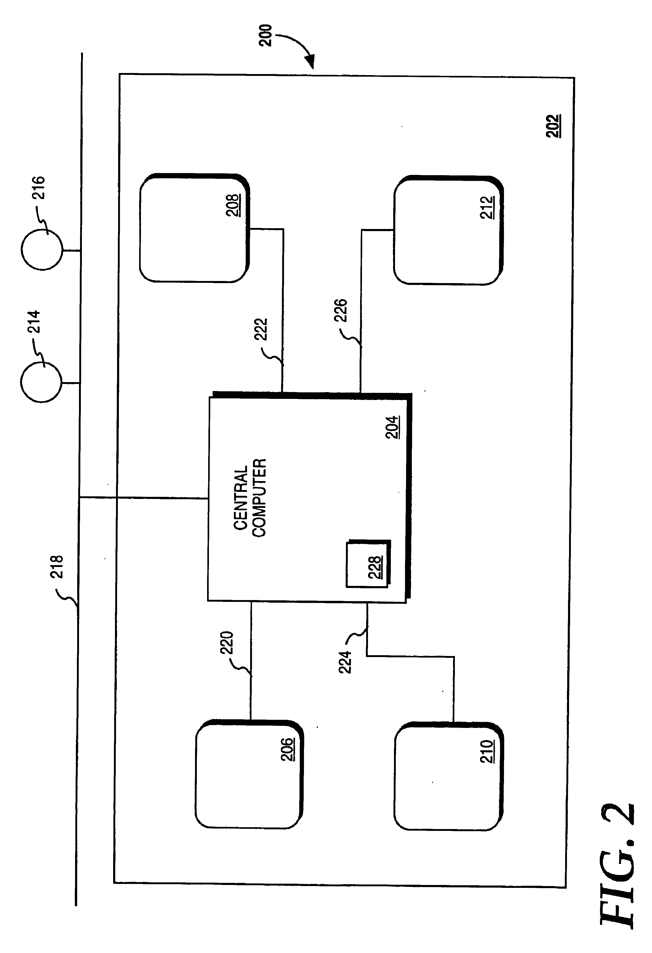
FIG. 2 is a block diagram of a system 200 which can be used with the computer implemented method of the present invention. System 200 is applicable to common environment 202. In this embodiment, common environment 202 is a house. In other embodiments, environment 202 can be, for example, a factory, a large commercial building, or any other environment in which devices are grouped. Environment 202, in this embodiment, includes devices 206, 208...


PUM


Abstract

A method for monitoring a plurality of devices in a common environment. The method comprises the steps of receiving usage information from one of the devices and storing the usage information on a memory device of a computer. The method further comprises the steps of using the computer to automatically access a remote database containing information regarding the device and transmitting the stored usage information to the remote database. The information is received from the remote database and an action to be taken by the device is generated using the information from the remote database and the stored usage information.

Description

FIELD OF THE INVENTIONThe present invention is in the field of automatic monitoring and control of devices by a central computer. More particularly, the present invention is in the field of automatic monitoring and control of devices by a central computer that accesses a remote database.BACKGROUND OF THE INVENTIONSystems currently exist to monitor and control devices in an environment such as a house, factory, or commercial office building. Current systems can include stand-alone units connected to a single device. For example, such units include a module connected to a lamp where the module is programmable to control the times the lamp turns on and off. Current systems also include central controllers such as personal computers (PCs) that function as central controllers for a variety of modules that are connected to individual devices.Controllers can communicate with controlled devices in a variety of ways. For example, a common communication method uses existing alternating curren...

Claims


Application Information

Patent Timeline
Patent Type & Authority Patents(United States)
IPC IPC(8): G05B23/02H04L29/06H04L29/08G06F11/34
CPCH04L29/06G05B23/0283G05B23/0213H04L67/12G06F11/3466H04L69/329H04L9/40
Inventor POISNER, DAVID I.
Owner INTEL CORP
Why Eureka
Try Eureka