Device in a portable power tool

a power tool and portable technology, applied in the field of portable power tools, can solve the problems of heavy tools, complex tools, and inability to properly latch the latch solution, and achieve the effect of convenient installation and removal of the blad

Inactive Publication Date: 2005-01-18
HUSQVARNA AB
View PDF10 Cites 8 Cited by
  • Summary
  • Abstract
  • Description
  • Claims
  • Application Information

AI Technical Summary

Problems solved by technology

Since clearing saws work in very rough conditions, the mechanical latching solutions do not always work properly because of the dirt, dust wood particles, and other debris that can interfere with the mechanical latches during use.
This solution might include a releasable stop device that keeps the pin in the locking position, however, such a mechanism would make the tool heavier and more complex.

Method used


Image

  • Device in a portable power tool
  • Device in a portable power tool

Examples


Embodiment Construction

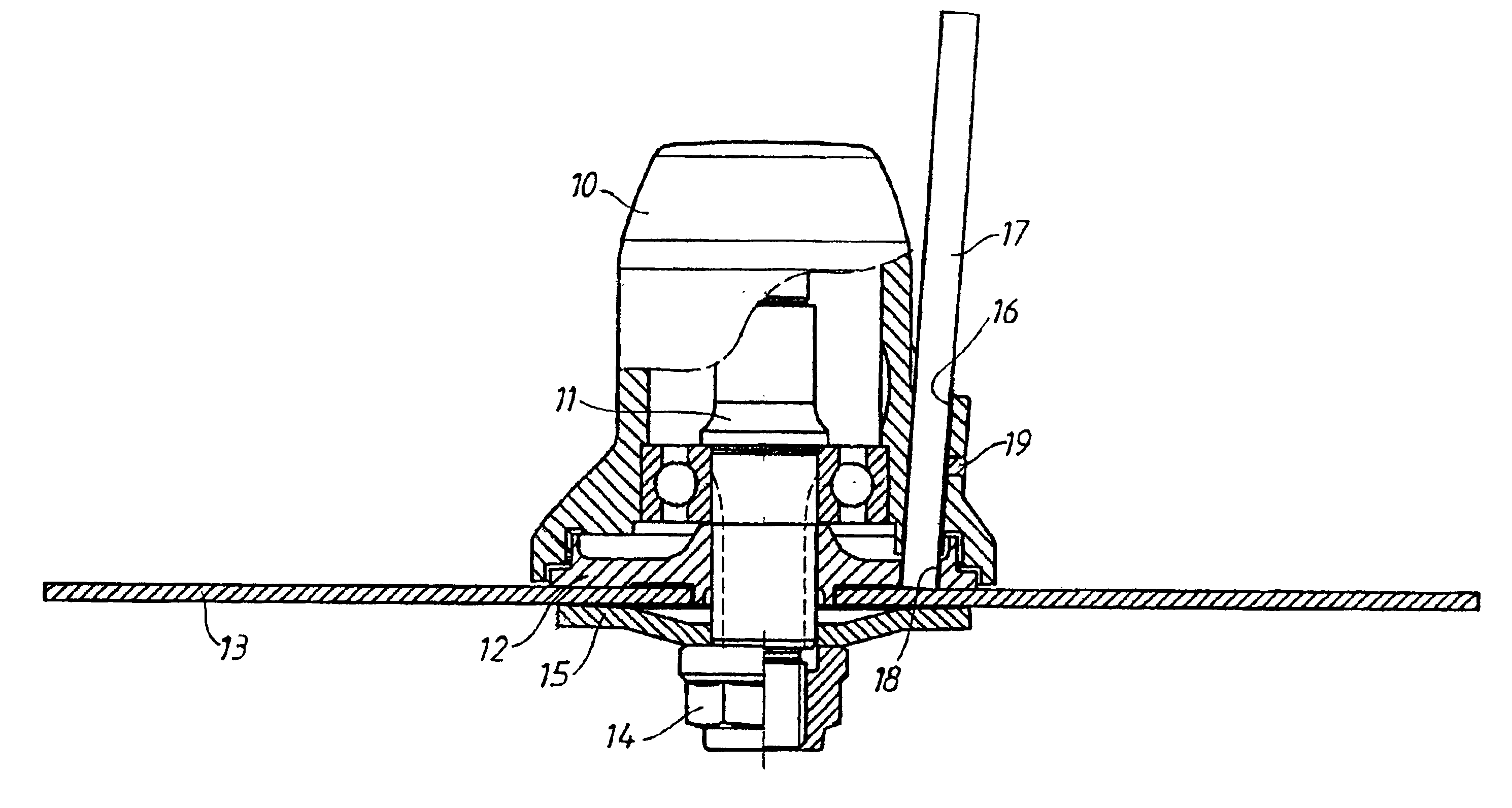
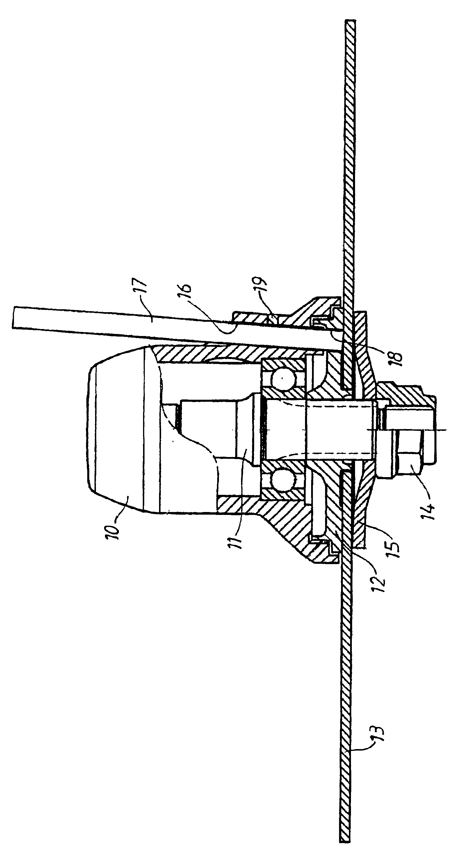
A housing 10, including an engine powered gearbox, is connected to a user-held guide bar, not shown in the drawing, of a clearing saw. The gearbox includes a toothed transmission gear, not shown in the drawing, with a rotatably driven shaft 11. A fastening device 12 for holding in place a cutting tool 13 is attached to the low end of the shaft 11 as shown. The cutting tool 13, for example a circular saw blade, is attached to the fastening device by a nut 14 screwed on to the threaded end of shaft 11, and an elastic washer 15. The nut 14 can be unscrewed from the threaded end of the shaft 11 and released to make it possible to replace the cutting tool 13.

The gearbox housing 10 has on one of its sides an almost vertical hole 16. Inside the hole 16, a locking pin 17 is inserted, the pin 17 being made of a magnetic material, for example iron. The lower end of the locking pin 17 can be located or inserted in a matching opening or hole 18 in the fastening device 12. The surrounding housin...


PUM

PropertyMeasurementUnit
distanceaaaaaaaaaa
magneticaaaaaaaaaa
forceaaaaaaaaaa

Abstract

A locking assembly for a portable, engine-powered, hand tool, such as a clearing saw. To facilitate removal and installation of a rotatable cutting tool (13), a rotatable shaft (11) driving the cutting tool is locked against rotation by a movable locking pin (17) of magnetic material that is secured in a locking position by a magnet (19) carried by a housing of the tool supporting the rotatable shaft.

Description

BACKGROUND OF THE INVENTIONThe present invention relates in general to portable, engine-powered, hand tools, and more specifically, to a clearing saw with a changeable circular saw blade. Such tools include an engine, a housing and a rotatable drive shaft connected to a rotating cutting tool, such as a circular saw blade, that is releasably fastened to the end of the shaft. A locking pin is movable in an axial direction into a hole in the shaft, or a part attached to the shaft, to fix the shaft in a non-rotating mode in relation to the housing to facilitate installation and removal of the cutting tool. In portable, engine-powered, hand tools like clearing saws, the cutting tool is fastened to the shaft, extending from a gear box, for example, bu a nut screwed on to a threaded end of the shaft. In order to facilitate the changing of the cutting tool, the shaft must be stopped from rotating relative to the housing to make it possible to rotatably release or fasten the nut. The shaft i...

Claims


Application Information

Patent Timeline
Patent Type & Authority Patents(United States)
IPC IPC(8): B27B5/30B27B5/00B27B5/38A01D34/76A01G3/08B27B9/00
CPCB27B5/38B27B5/30Y10T83/7747Y10T83/9379
Inventor JOHANSSON, JORGEN
Owner HUSQVARNA AB
Why Eureka
Try Eureka