AI technical title is built by Patsnap AI team. It summarizes the technical point description of the patent document.
a firearm and secure technology, applied in the field of firearm holders, can solve the problems of preventing authorized users from having immediate access to their weapons, not providing sufficient quick and ready access to firearms for authorized users, etc., and achieve the effect of easy and quick removal
Inactive Publication Date: 2005-01-18
PAINTER TERRY M
View PDF21 Cites 127 Cited by
Summary
Abstract
Description
Claims
Application Information
AI Technical Summary
This helps you quickly interpret patents by identifying the three key elements:
Problems solved by technology
Method used
Benefits of technology
Benefits of technology
According to a preferred embodiment, a bore shaft is mounted on the hinged plate, with the bore shaft extending into the firearm. Thus, the firearm is mounted on the plate by the bore shaft. When the plate is in a first, closed, position, the holder base prevents the gun from being removed from the bore shaft, but when a motivating member rotates the plate about the hinge to a second position, the gun can be easily and quickly removed from the bore shaft in the ready-to-use orientation.
Problems solved by technology
However, a problem with placing impediments on the use of firearms is that the impediments often hinder authorized users from having immediate access to their weapons.
The devices described in these patents have a number of disadvantages; however, a common disadvantage of all of them is that they do not provide sufficiently quick and ready access to firearms for authorized users.
Method used
Image
Click on the blue label to locate the original text in one second.
Reading with bidirectional positioning of images and text.
Examples
Embodiment Construction
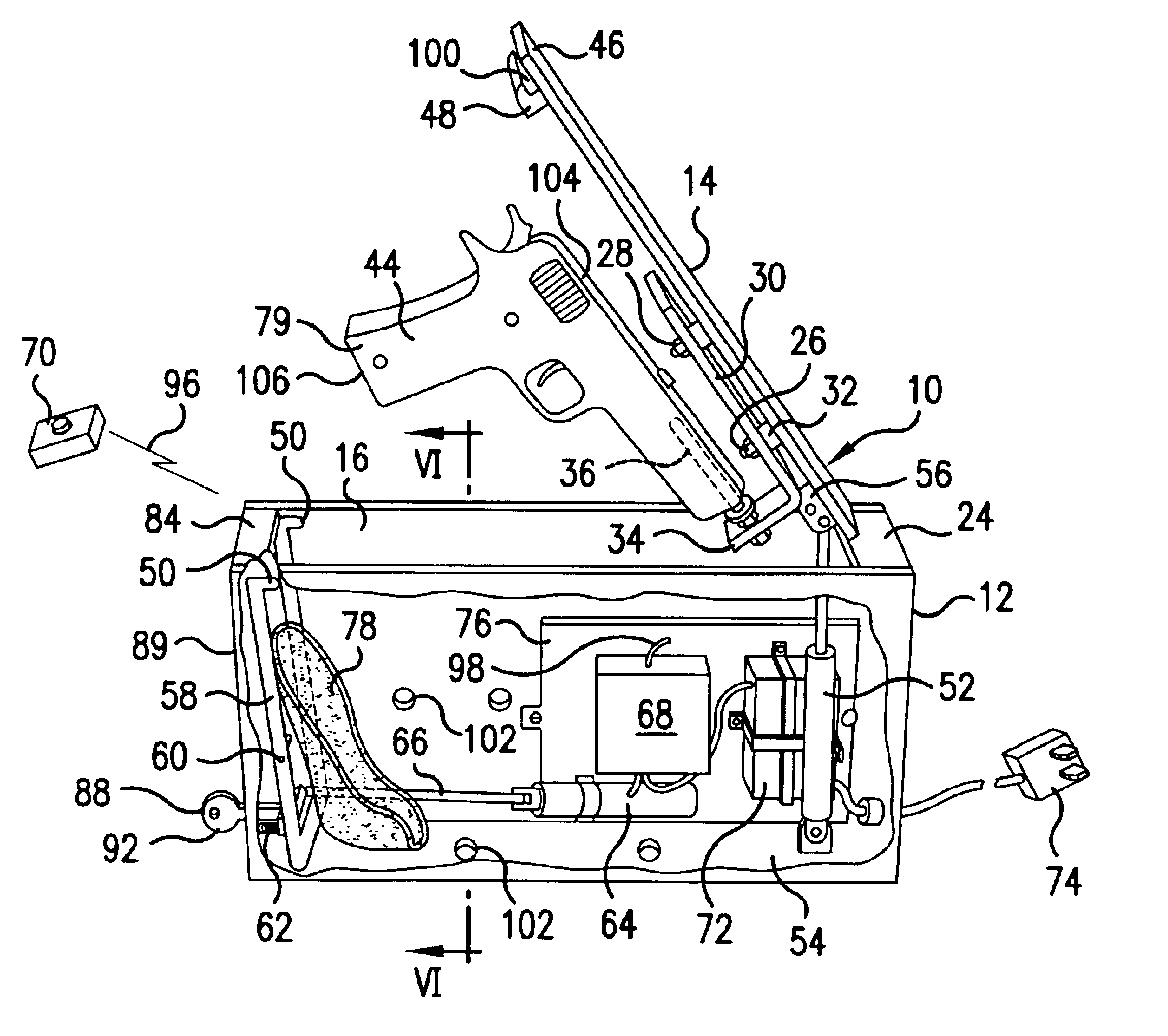
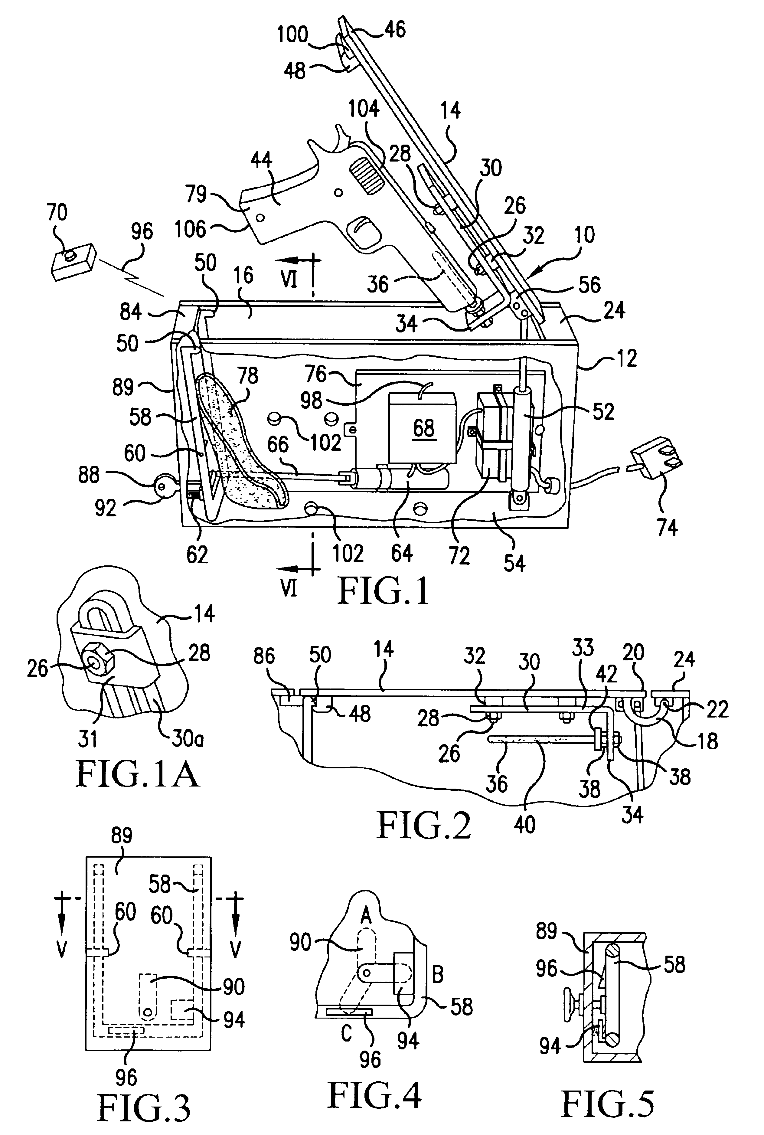
A firearm holder 10 includes a holder base 12 with associated structure and a plate 14 that is hingedly attached to the holder base 12. In the embodiment of the invention depicted in the drawings, the holder base 12 is a box 12 and the plate 14 is a lid 14 for covering an opening 16 in the box 12. The plate, or lid, 14 has a semicircular hinge member 18 (shown in FIG. 2 but omitted in FIG. 1 for purposes of illustration) that is rigidly attached to an underside of the lid 14 at a first end portion 20 of the lid, and is pivotally attached at 22 to an underside of a first top member 24 of the box 12. Thus, the lid 14 can hinge on the box 12 between a first, closed, position, as depicted in FIG. 2, and a second, open, position as depicted in FIG. 1.
The plate, or lid, 14 has threaded studs 26 welded to the underside thereof on which nuts 28 hold an L-shaped bracket 30 to the lid 14, but spaced therefrom by spacers 32. An attached leg 33 of the bracket 30 has attachment slots (or it coul...
PUM
Abstract
A secure firearm holder (10) includes an outwardly swinging hinged plate (14) that is hinged to a holder base (12) with a gun (44) mounted at a side of the plate in a ready-to-use orientation when the plate swings outwardly. In a preferred embodiment, a bore shaft (36) is mounted on the hinged plate, the bore shaft extending into the firearm. When the plate is in a first, closed, position, the holder base prevents the gun from being removed from the bore shaft, but when a motivating member (52) rotates the plate to a second position, the gun can be easily and quickly removed from the bore shaft from a ready-to-use orientation. The motivating member biases the lid toward the second position but is held closed in the first position by a latch (50), which latch is remotely releasable. A locking mechanism has three positions: a totally-locked position (B) for locking the latch (50) against remote release of the lid; an active position (A) for allowing remote release of the lid; and a manual-release position (C) for releasing the lid manually.
Description
BACKGROUND OF THE INVENTIONThis invention relates generally to the art of weapon holders, and more specifically to secure firearm safes or holders.In recent years a great deal of emphasis has been placed upon preventing unauthorized and improper use of firearms. Quite often such efforts have been directed toward placing impediments to accessing firearms, such as locking firearms in holders, or safes. However, a problem with placing impediments on the use of firearms is that the impediments often hinder authorized users from having immediate access to their weapons. In this regard, a number of US patents describe handgun storage cases, gun locks, gun safes and the like for storing handguns, a few of these being: U.S. Pat. No. 5,056,342 to Prinz; U.S. Pat. No. 5,118,175 to Costello; U.S. Pat. No. 5,236,086 to MacTaggart; U.S. Pat. No. 5,683,021 to Satina; U.S. Pat. No. 5,881,584 to Brunoski et al.; U.S. Pat. No. 5,901,589 to Cordero; U.S. Pat. No. 5,987,941 to Zocco; U.S. Pat. 6,405,8...
Claims
Application Information
Patent Timeline
Application Date:The date an application was filed.
Publication Date:The date a patent or application was officially published.
First Publication Date:The earliest publication date of a patent with the same application number.
Issue Date:Publication date of the patent grant document.
PCT Entry Date:The Entry date of PCT National Phase.
Estimated Expiry Date:The statutory expiry date of a patent right according to the Patent Law, and it is the longest term of protection that the patent right can achieve without the termination of the patent right due to other reasons(Term extension factor has been taken into account ).
Invalid Date:Actual expiry date is based on effective date or publication date of legal transaction data of invalid patent.

