Triaxial angular rate and acceleration sensor

a technology of acceleration sensor and angular rate, which is applied in the direction of turn-sensitive devices, couplings, instruments, etc., can solve the problem of not measuring angular rate, and achieve the effect of preventing angular acceleration sensitivity

Inactive Publication Date: 2005-01-18
HONEYWELL INT INC
View PDF12 Cites 31 Cited by
  • Summary
  • Abstract
  • Description
  • Claims
  • Application Information

AI Technical Summary

Benefits of technology

In accordance with a further feature of the invention, the sensor may be designed to prevent angular acceleration sensitivity. In one embodiment of such a design, the first and second sets of accelerometers are not coplanar. Rather, the first set of accelerometers lie in a first plane while the second set of accelerometers lie in a second plane that is generally parallel to the first plane. The input axes of the first set of accelerome...

Problems solved by technology

Although this accelerometer may be used to measu...

Method used


Image

  • Triaxial angular rate and acceleration sensor
  • Triaxial angular rate and acceleration sensor
  • Triaxial angular rate and acceleration sensor

Examples


Embodiment Construction

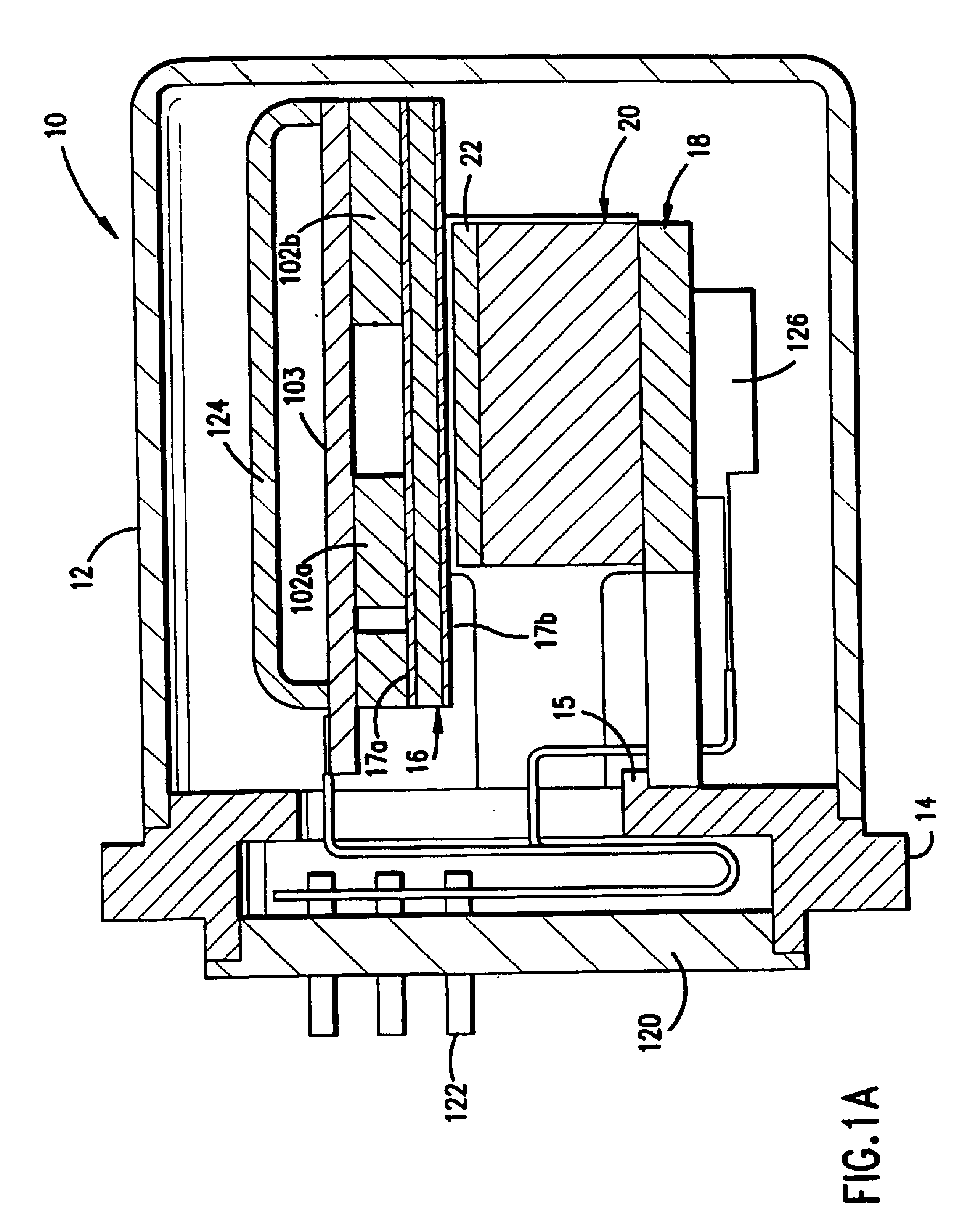
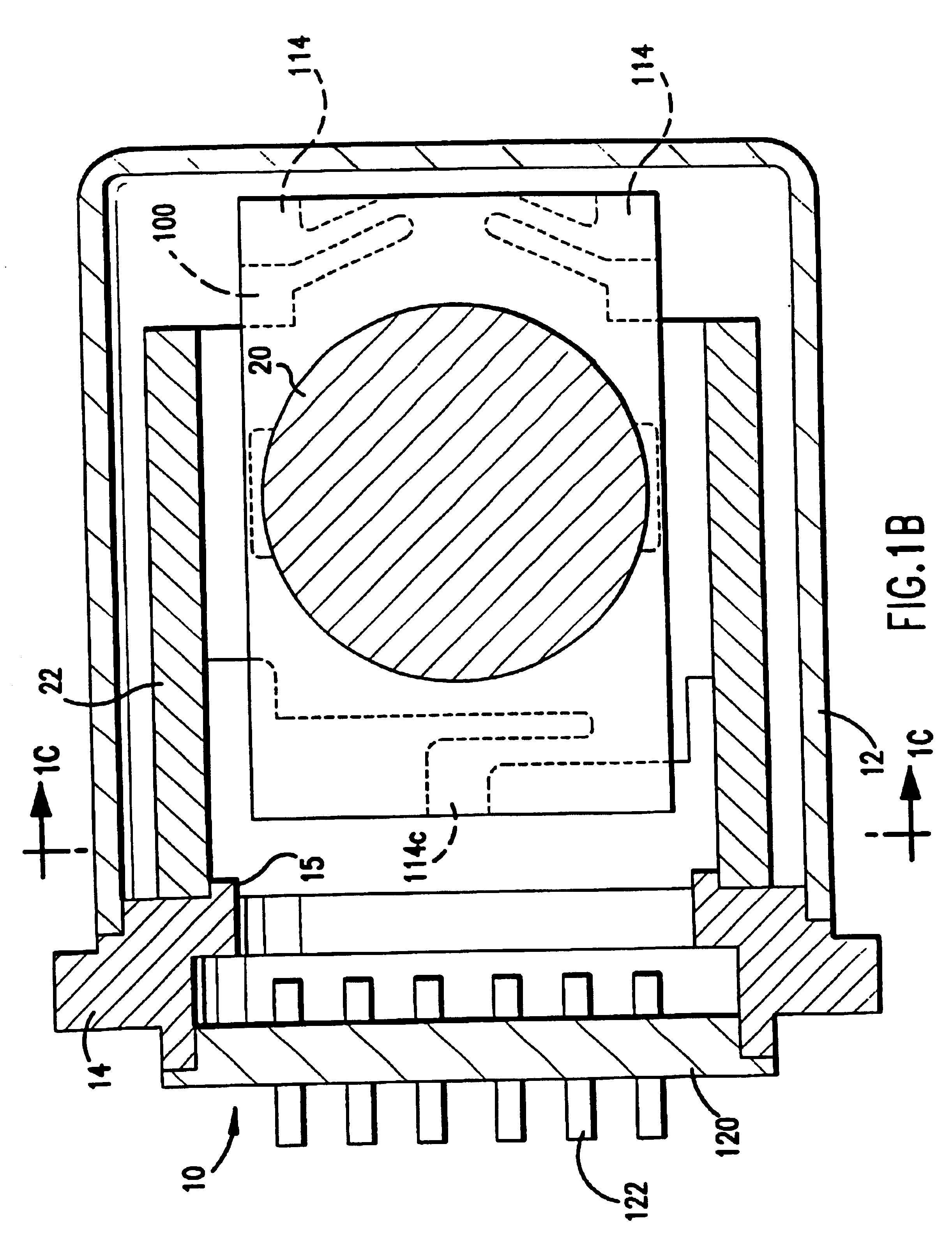
Referring now to the drawings, FIGS. 1A, B, C and D show the arrangement of a rate and acceleration sensor 10 according to the present invention. The sensor 10 includes a shell 12 housing a unitary substrate 16, which is illustratively made of silicon and in which is formed, illustratively by micro-machining, a pair of accelerometers 32a and 32b disposed in side-by-side relation such that their input axes 38a and b are disposed in opposite directions (see FIG. 1D). The sensor 10 also includes a unitary magnet 20 and a flux path assembly 18, which provides a magnetic path for directing the flux emanating from the magnet 20 through the substrate 16 and its first and second accelerometers 32a and b. As will be explained, the configuration and disposition of the accelerometers 32a and b within the substrate 16 permits a simple, straightforward magnetic flux path to effect the operation of the dithering motion and the vibration of a sensor element of the accelerometers 32a and b.

Referri...


PUM


Abstract

A triaxial sensor substrate is adapted for use in measuring the acceleration and angular rate of a moving body along three orthogonal axes. The triaxial sensor substrate includes three individual sensors that are arranged in the plane of the substrate at an angle of 120 degrees with respect to one another. Each sensor is formed from two accelerometers having their sensing axes canted at an angle with respect to the plane of the substrate and further being directed in opposite directions. The rate sensing axes thus lie along three orthogonal axes.
In order to reduce or eliminate angular acceleration sensitivity, a two substrate configuration may be used. Each substrate includes three accelerometers that are arranged in the plane of the substrate at an angle of 120 degrees with respect to one another. The sensing axes of the accelerometers of the first substrate are canted at an angle with respect to the plane of the first substrate toward the central portion thereof so that they lie along three skewed axes. Similarly, the sensing axes of the accelerometers of the second substrate are canted at an angle with respect to the plane of the second substrate away from the central portion thereof so that they lie along same three but oppositely directed axes. The sensing axes of the first and second substrates are aligned to prevent angular acceleration sensitivity.

Description

FIELD OF THE INVENTIONThe present invention relates to micromachined devices used for measuring angular rate and acceleration. More particularly, the present invention relates to a triaxial angular rate and acceleration sensor for use in inertial measurement units that may be micromachined from a single substrate.BACKGROUND OF THE INVENTIONInertial measurement units (IMUs) are critical to the proper operation of inertial navigation and guidance systems. Such systems are used on ships, aircraft, spacecraft, etc.A typical IMU utilizes a cluster of three accelerometers and three gyros mounted to a structure which is shock isolated. The three accelerometers are used to measure linear acceleration while the gyros are used to measure angular rate.U.S. Pat. No. 4,920,801, the mathematical equations of which are hereby incorporated by reference, is directed to a monolithic accelerometer capable of sensing linear acceleration in three orthogonal directions. The accelerometer utilizes three c...

Claims


Application Information

Patent Timeline
IPC IPC(8): F02G1/044F02G1/00F16L37/00F16L37/24G01P15/10G01P15/18G01P15/08G01P15/097G01C19/56G01C19/5719G01C19/574
CPCF02G1/044F02G1/0445F16L37/24G01C19/56G01P15/18G01C19/574G01P15/0802G01P15/097G01C19/5719G01P2015/0828
Inventor HULSING, II, RAND H.
Owner HONEYWELL INT INC
Why Eureka
Try Eureka