Coffee brewer

a coffee brewer and coffee technology, applied in beverage vessels, household appliances, kitchen equipment, etc., can solve the problems of unattractive residue, unfavorable high-quality coffee brewing, so as to achieve rapid and consistent high-quality coffee brewing, quickly and easily calibrate a metered volume of hot water, and easy removal

Inactive Publication Date: 2005-01-18
ZOHAR WATERWORKS
View PDF13 Cites 37 Cited by
  • Summary
  • Abstract
  • Description
  • Claims
  • Application Information

AI Technical Summary

Benefits of technology

In accordance with the invention, an improved coffee brewer is provided for rapid and consistent high quality brewing of coffee in a commercial environment such as in an office or the like, or in a residential environment. The coffee brewer incorporates a precision calibration or set up mode for quickly and easily calibrating a metered volume of hot water to be delivered via a spray head to a brew basket during each brew cycle. In addition, the coffee brewer includes a removable rail unit for supporting the brew basket in association with the spray head, wherein the rail unit and spray head are quickly and easily removable for periodic cleaning.
A control panel mounted on a housing of the coffee brewer includes one or more control buttons or the like for quick and easy operation. In accordance with one aspect of the invention, the control panel is operable in association with a main power switch mounted, for example, on a rear side of the brewer housing, for initiating a set up calibration mode used for controllably selecting the precise metered volume to be dispensed on each brew cycle. More particularly, with the main power switch in an “off” position, a “brew” button on the control panel is depressed and held while the main power switch is turned “on”. Then, with a measuring pitcher placed beneath the spray head, and with the brew basket removed, the “brew” button is depressed once to start water flow to the spray head and a second time to stop such water flow when the measuring pitcher fills to the desired dispensed volume. The coffee brewer will thereafter dispense a metered volume of hot water for each brew cycle to produce the same volume of brewed coffee, with the actual dispensed water volume being increased by a factor of about 10% to account for residual water remaining within the coffee grounds at the conclusion of each brew cycle.
In accordance with a further aspect of the invention, the removable rail unit supports the brew basket for slide-in and slide-out placement beneath the spray head. In a preferred form, the rail unit is removably mounted on the brewer housing as by quarter-turn or snap-fit attachment or the like of a spray head cap onto the spray head. If and when accumulated coffee residue makes it desirable to clean the rail unit, the rail unit and associated spray head cap can be separated quickly and easily from the housing for appropriate cleaning and / or replacement. Similarly, with the rail unit removed, the spray head can also be removed as by unthreading from the downstream end of a dispense conduit for appropriate cleaning and / or replacement.

Problems solved by technology

This set up calibration procedure can be undesirably time consuming, and does not preclude subsequent volumetric variations in the event of subsequent water supply pressure fluctuations.
In addition, coffee brewers routinely encounter a build-up of oil-based residue particularly on the coffee pot, as well as on the brew basket and adjoining surfaces of a machine housing.
Such residue is unsightly and unattractive, and also can detract from the desirable fresh flavor of brewed coffee.
With prior coffee brewers, however, surfaces adjoining the brew basket are typically hard to reach and access for effective cleaning.
Moreover, when a glass coffee pot is used, cleaning thereof is accompanied by a risk of glass breakage and associated safety hazard, in addition to requiring a replacement coffee pot before use of the coffee brewer can be resumed.

Method used


Image

  • Coffee brewer
  • Coffee brewer
  • Coffee brewer

Examples


Embodiment Construction

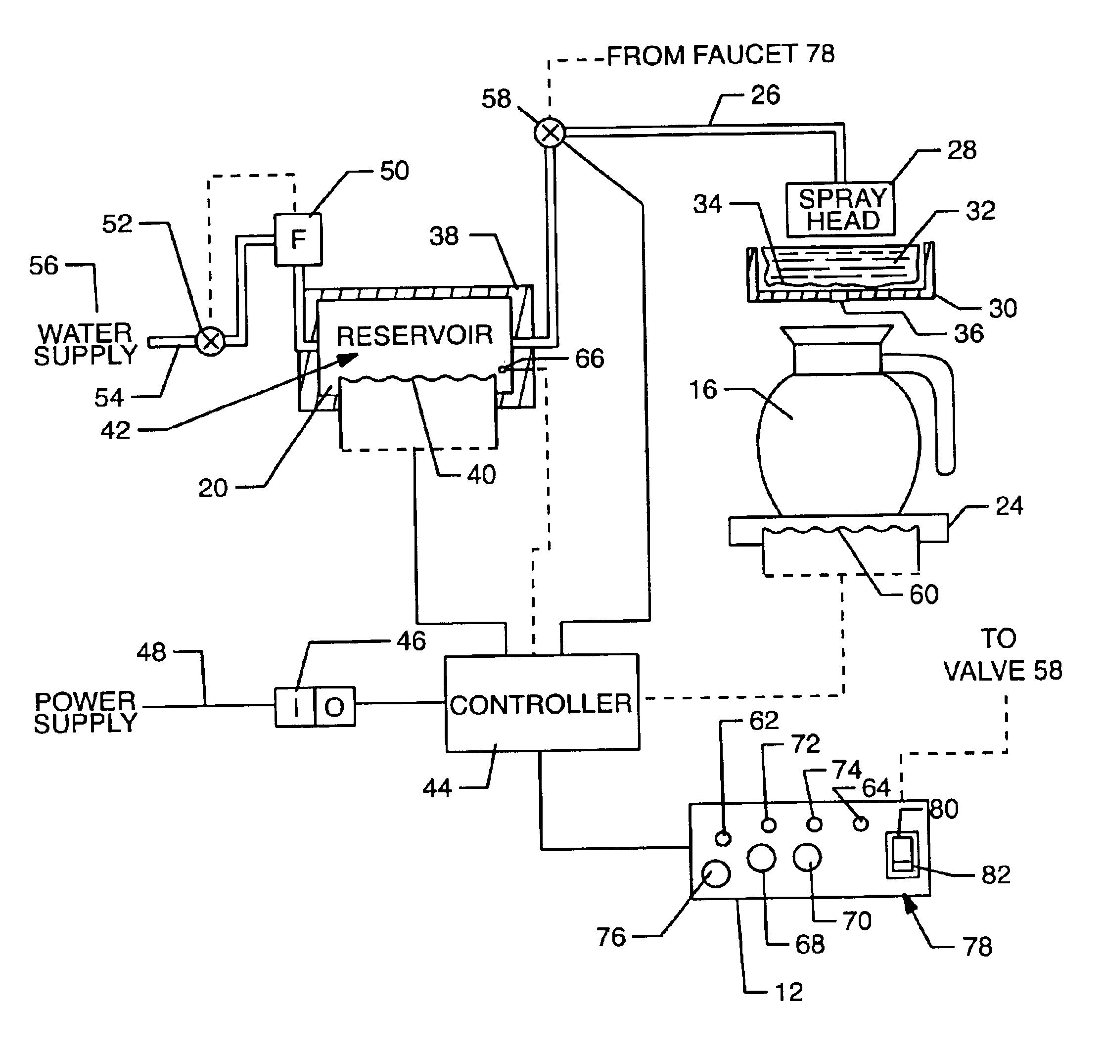
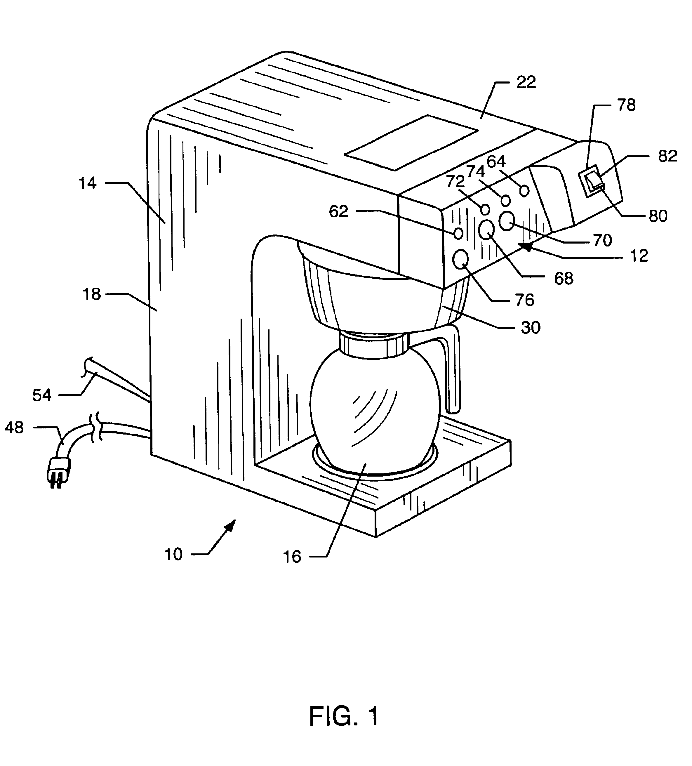
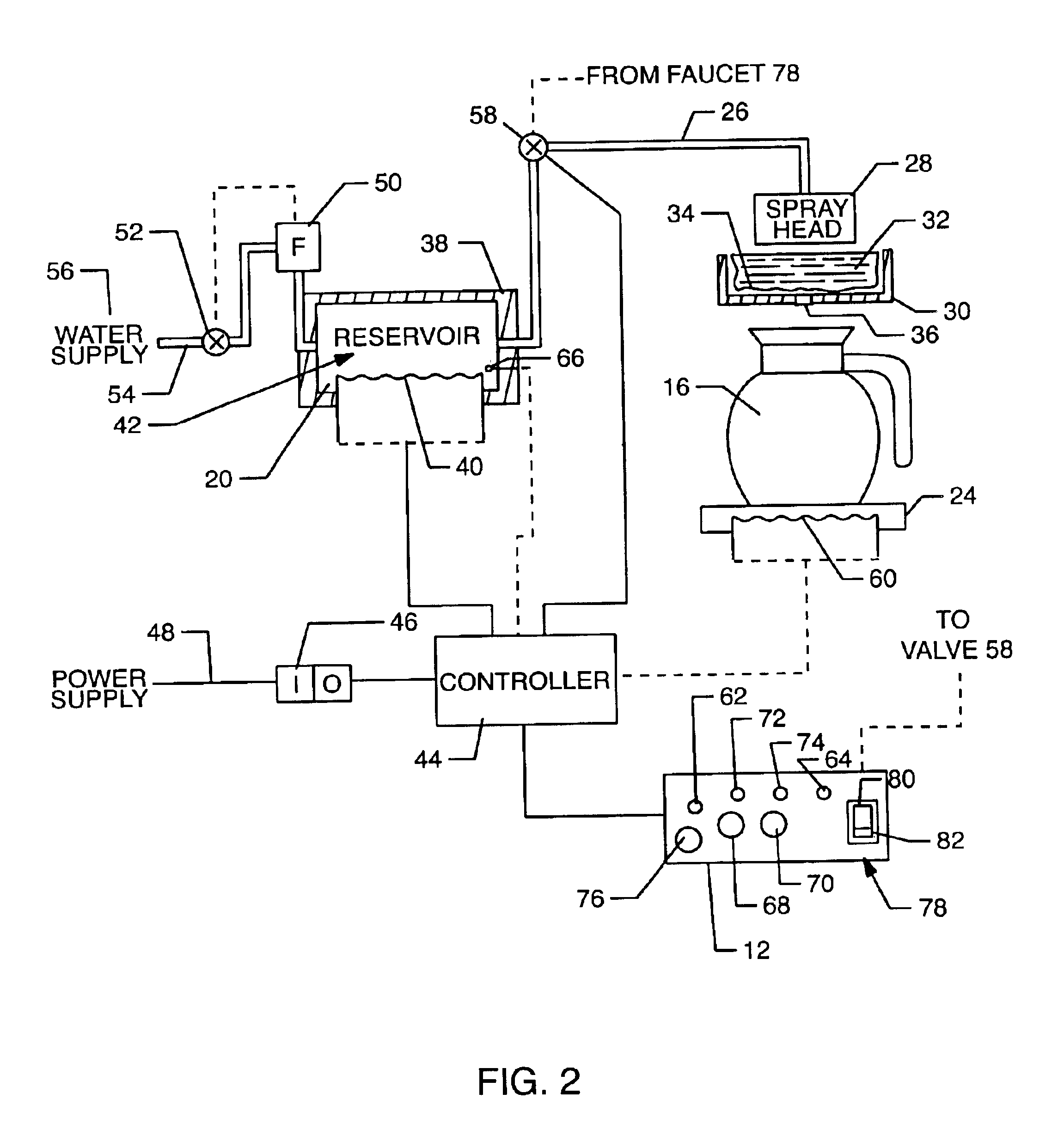
As shown in the exemplary drawings, a coffee brewer referred to generally in FIG. 1 by the reference numeral 10 is provided for rapid and consistent high quality brewing of coffee in a commercial environment such as in an office or the like, or in a residential environment. The coffee brewer 10 includes a control panel 12 located on the front of a brewer housing 14 for selectively operating the machine to produce fresh brewed coffee that is collected within a coffee pot or decanter 16. In accordance with improved features of the coffee brewer 10, the control panel 12 can be operated in a set up calibration mode for precision calibration of a metered volume of hot water to be dispensed during each brew cycle. In addition, key components of the coffee brewer 10 are quickly and easily disassembled from the housing 14 to facilitate periodic cleaning thereof.

The coffee brewer 10 is shown in FIG. 1 with the brewer housing 14 having a relatively compact size and shape suitable for countert...


PUM


Abstract

An improved coffee brewer is provided for rapid and consistent high quality brewing of coffee. The coffee brewer includes a control panel for initiating a brew cycle wherein a metered volume of hot water is delivered from an insulated water reservoir via a spray head to mix with coffee grounds contained within a filter-lined brew basket, with the resultant brewed coffee draining into an underlying pot preferably such as an insulated carafe. The control panel is further operable for precision calibration of the metered water volume delivered to the brew basket for each brew cycle. In addition, the coffee brewer incorporates a removable rail unit for supporting the brew basket, wherein the rail unit and spray head are removable quickly and easily disassembled for periodic cleaning.

Description

BACKGROUND OF THE INVENTIONThis invention relates generally to improvements in devices and systems for brewing coffee or the like. More particularly, this invention relates to an improved coffee brewer machine designed for quick and easy set up calibration for consistent dispensing of a predetermined metered volume of hot water during each brew cycle. In addition, this invention relates to an improved coffee brewer machine designed for quick and easy removal of selected components thereof for facilitated and periodic cleaning.Coffee brewers are generally known in the art for drip process brewing of hot coffee in a commercial environment such as in an office or the like. Such coffee brewers typically include a hot water reservoir which may be coupled to a tap water supply, and from which a controlled volume of hot water is delivered to an upwardly open brew basket having a porous filter containing a quantity of ground coffee mounted therein. The hot water intermixes with the coffee g...

Claims


Application Information

Patent Timeline
Patent Type & Authority Patents(United States)
IPC IPC(8): A47J31/52A47J31/40A47J31/44
CPCA47J31/402A47J31/4403A47J31/52A47J31/446A47J31/4478A47J31/4439A47J31/5253
Inventor DROBECK, R. GREGORY
Owner ZOHAR WATERWORKS
Why Eureka
Try Eureka