Stormwater treatment apparatus and method

a treatment apparatus and a technology for stormwater, applied in water cleaning, other chemical processes, separation processes, etc., can solve the problems of high property values, soil conditions, and inability to use conventional, space-intensive stormwater bmp's such as detention ponds, and achieve the effect of maintaining a compact footprint or plan area

Inactive Publication Date: 2007-03-29
JENSEN PRECAST
View PDF99 Cites 31 Cited by
  • Summary
  • Abstract
  • Description
  • Claims
  • Application Information

AI Technical Summary

Benefits of technology

[0078] One of the failings of prior “flow-through” systems was their inability to settle small particles from smaller storm flows without resuspending those particles in later large storm flows due to turbulence and currents that reach all areas of the prior vaults. The present apparatus, by creating an active pool that fills, holds and drains immediately above an inactive permanent pool, eliminates small particle re-suspension. Even in prior systems, simply applying baffles to create a physical barrier to sediments moving horizontally through the system, without creating a permanent pool, ...

Problems solved by technology

Space constraints, high property values, soil conditions, and the proximity of other building foundations often preclude the use of conventional, space-intensive stormwater BMP's such as detention ponds.
Vault-type treatment technologies have been widely used for stormwater treatment in urban areas; however, the effectiveness of these devices for removal of suspended solids and oil and grease has been only marginal.
A great weakness of these types of devices has been that large storm events tend to flush out the system, thereby releasing pollutants that were previously removed.
All of these devices are somewhat effective at settling out particles down to a certain size or specific gravity, but none of these devices are effective at removing the very small size range of particles that make up the majority of toxic pollutants in storm water runoff.
However, such systems provide little or no detention capture volume to mitigate the runoff peaks for small or large runoff events.
In other words, these systems function as flow-through devices, resulting in the lack of capture volume and overall poor treatment performance.
Specifically, much of the settleable materials trapped or deposited during more numerous...

Method used


Image

  • Stormwater treatment apparatus and method
  • Stormwater treatment apparatus and method
  • Stormwater treatment apparatus and method

Examples


Embodiment Construction

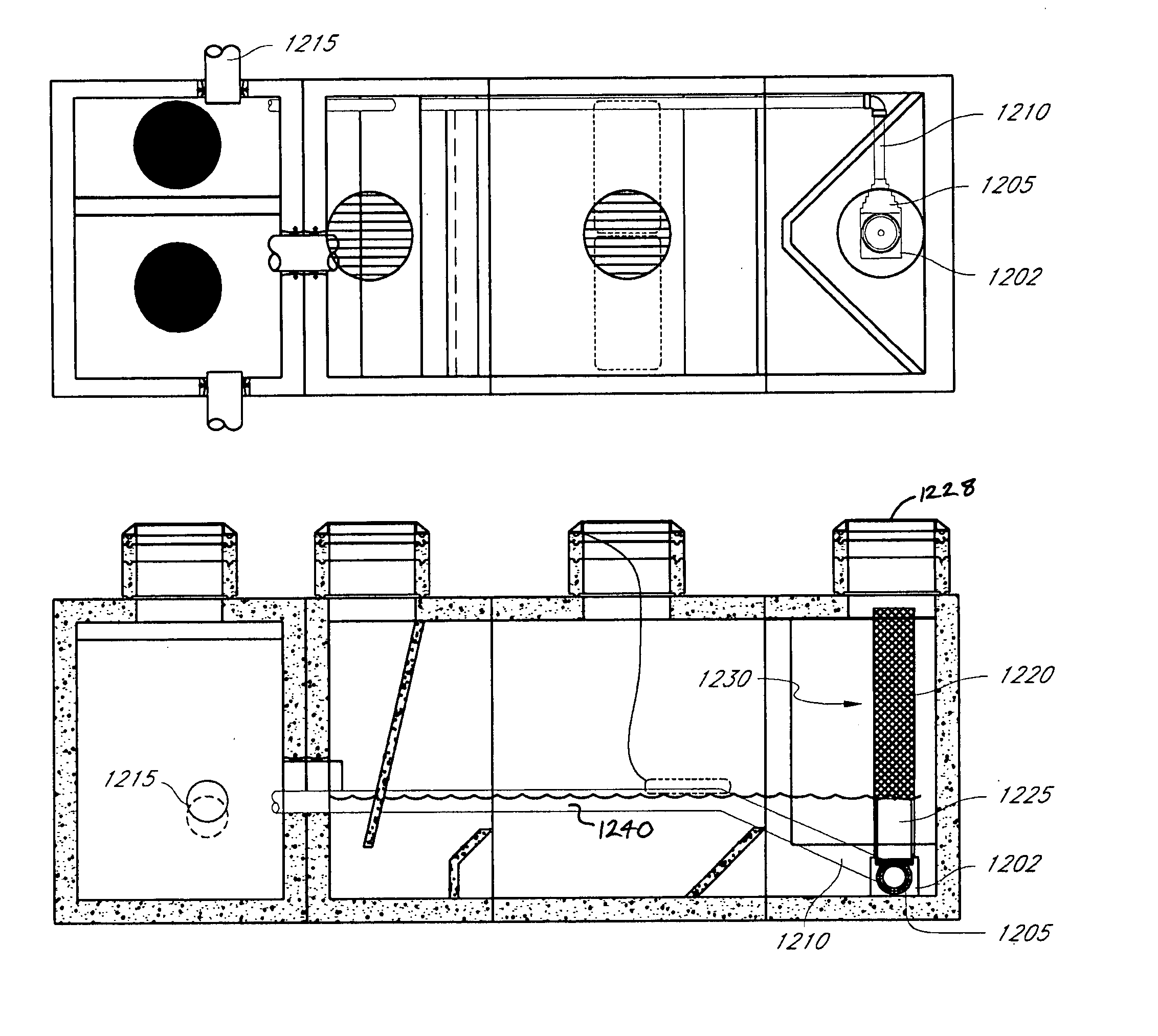
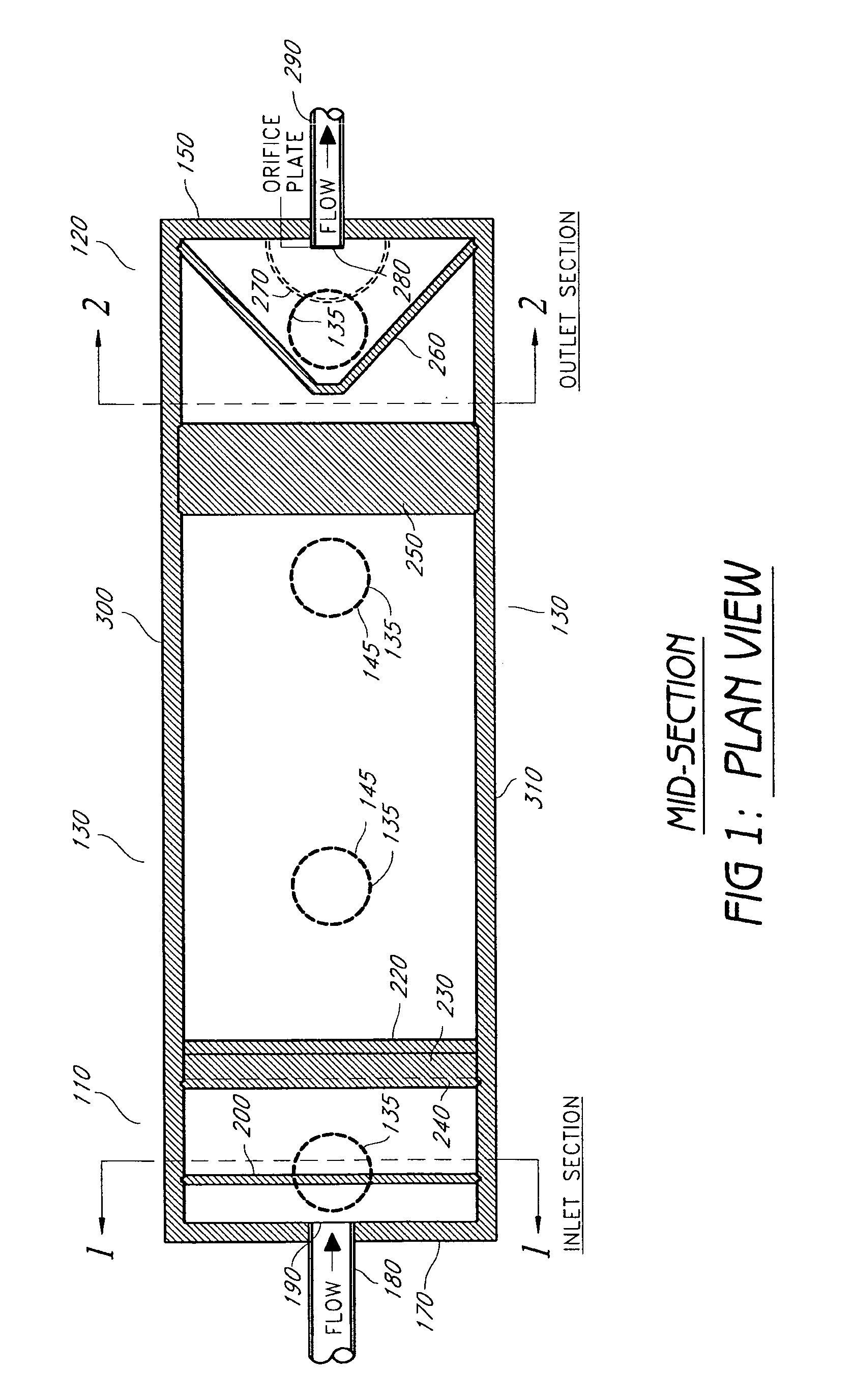
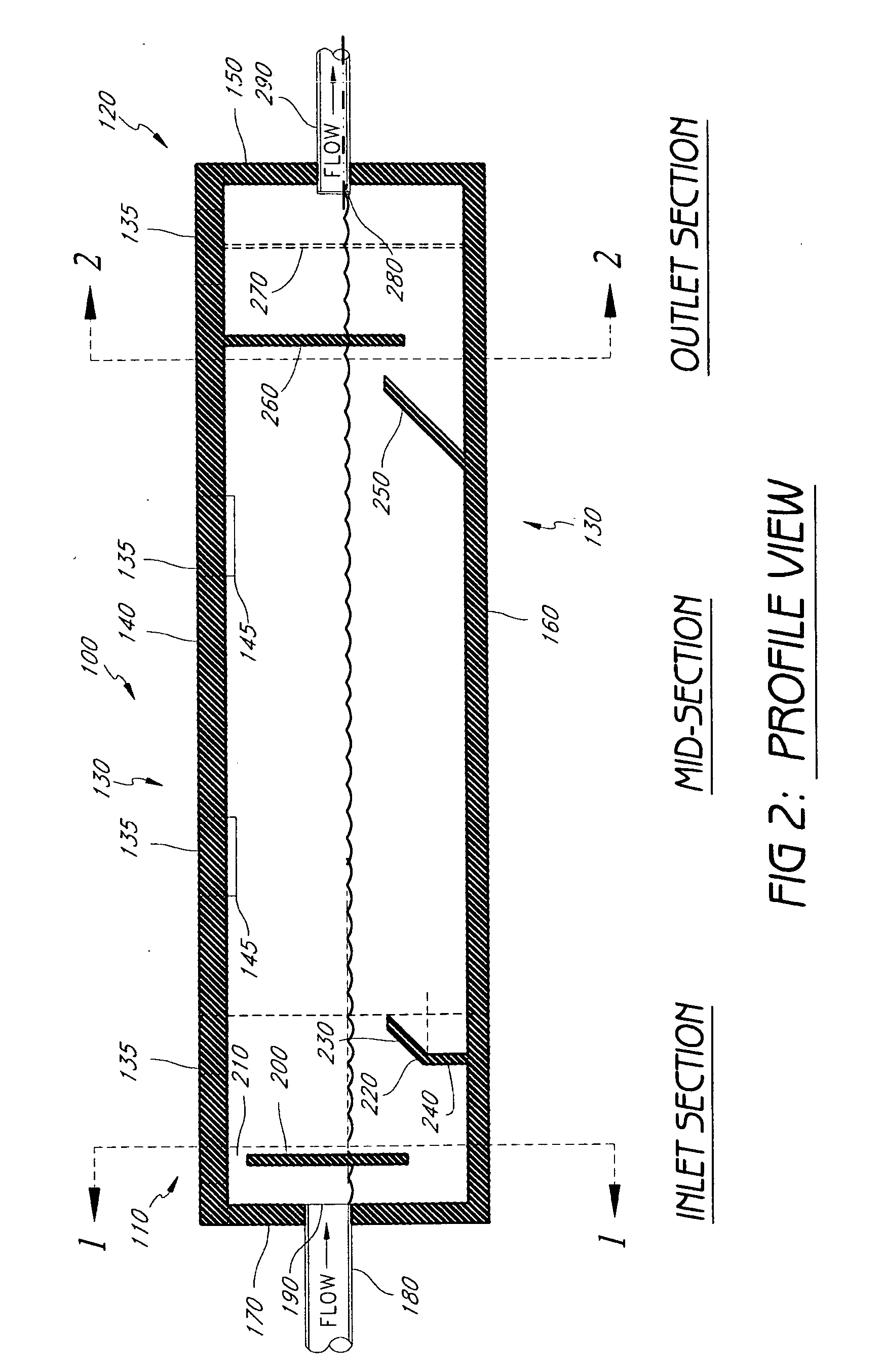
[0100] The drawings illustrate one embodiment of an apparatus 100 for separation of pollutants that are less and more dense than water from stormwater runoff. Referring to FIG. 1 and FIG. 2, the apparatus 100 consists of a top 140, a bottom 160, an inlet end 170, an outlet end 150, a left side 300, and a right side 310 (left and right are relative to the view FROM the inlet end 170 to the outlet end 150). These sides define a rectangular chamber with an inlet section 110, an outlet section 120, and one or more midsections 130.

[0101] The length of the most basic configuration of the apparatus 100 is desirably at most 20 ft, more desirably at most 18 ft 6 in, and, most preferably, 17 ft 6 in (inside dimension); and the width of the apparatus id desirably at most 10 ft, more desirably at most 8 ft 6 in, and, most preferably, 7 ft 6 in (inside dimension); the height of the apparatus is 6 ft or 8 ft (inside dimensions). Outside dimensions and inside dimensions may vary due to structural...


PUM

PropertyMeasurementUnit
Flow rateaaaaaaaaaa
Electrical resistanceaaaaaaaaaa
Shapeaaaaaaaaaa

Abstract

A liquid purification and separation apparatus for separation of pollutants in stormwater runoff is disclosed. This apparatus utilizes gravitational separation and tortuosity, resulting from a plurality of baffles both perpendicular to and oblique to the primary water flow direction, to trap substances less-dense and more-dense than water. The apparatus features improved resistance to pollutant remobilization through treatment of water volume rather than flow rates, using vertically stacked water columns of varying depths to settle small particles. An overflow structure diverts excessive liquid without interfering with purification and separation, and can be placed integrally within or external to the apparatus receptacle.

Description

RELATED APPLICATIONS [0001] This application is a continuation-in-part of U.S. patent application Ser. No. 11 / 356,433 filed Feb. 16, 2006 and, which is a continuation of U.S. patent application Ser. No. 10 / 681,766 filed Oct. 8, 2003 and issued Feb. 21, 2006 as U.S. Pat. No. 7,001,527, which is a divisional of U.S. patent application Ser. No. 10 / 084,837 filed Feb. 26, 2002 and issued Oct. 28, 2003 as U.S. Pat. No. 6,638,424, which is a continuation-in-part of U.S. patent application Ser. No. 09 / 487,097 filed Jan. 19, 2000 and issued Feb. 26, 2002 as U.S. Pat. No. 6,350,374. The disclosure of each of the foregoing applications is hereby incorporated by reference in its entirety into this application.BACKGROUND OF THE INVENTION [0002] 1. Field of the Invention [0003] Apparatus for treatment of stormwater runoff through volume-control-based detention and minimization of pollutant remobilization. [0004] 2. Description of the Related Art [0005] This invention relates generally to liquid p...

Claims


Application Information

Patent Timeline
IPC IPC(8): B01D21/00
CPCB01D21/0012B01D21/0024E03F5/14C02F2103/001C02F1/004B01D2221/12B01D21/2433B01D21/0042B01D21/02B01D21/2405B01D21/0039B01D21/0006B01D21/34Y02A20/152
Inventor STEVER, R. RUSSELLPHELPS, STEPHEN C.
Owner JENSEN PRECAST
Why Eureka
Try Eureka