System and method for auxiliary contact assembly

a technology of contact assembly and auxiliary contact, which is applied in the direction of electrical equipment, electromagnetic relay details, coupling device connections, etc., can solve the problems of improper installation of pushers, continuity test may not detect, and may not detect the face of movable contacts. to achieve the effect of eliminating the opportunity of incorrect assembly

Inactive Publication Date: 2005-01-18
SIEMENS IND INC
View PDF2 Cites 0 Cited by
  • Summary
  • Abstract
  • Description
  • Claims
  • Application Information

AI Technical Summary

Benefits of technology

In accordance with the invention there is provided a contact assembly for use in an electrical switching apparatus designed to eliminate opportunity of incorrect assembly.
It is still another feature of the invention that the pusher comprises a neck extending through an opening in the enclosure for engagement with the actuator and the enclosure comprises an asymmetric rib on one side of the opening and the pusher comprises an asymmetric notch in the top wall on one side of the neck receiving the rib to prevent incorrect assembly of the pusher in the enclosure.

Problems solved by technology

However, a problem exists in that a simple continuity test may not detect whether the incorrect stationary contacts are installed in such a design.
A simple continuity test will not detect whether the movable contact is facing in the correct direction.
An additional problem of a conventional contact assembly is the improper installation of the pusher.
If the pusher moves in a linear direction, and it is mistakenly mounted in an inverted position, then the movable contact will not line up properly with the stationary contacts.
However, incorrect assembly may not be obvious during installation until after the cover and housing forming the enclosure are riveted together and the pusher binds during testing.
At this point in the manufacturing process the problem is discovered, but the parts may not be salvageable.
These variations necessitate additional parts inventory resulting in loss of economies of scale.

Method used


Image

  • System and method for auxiliary contact assembly
  • System and method for auxiliary contact assembly
  • System and method for auxiliary contact assembly

Examples


Embodiment Construction

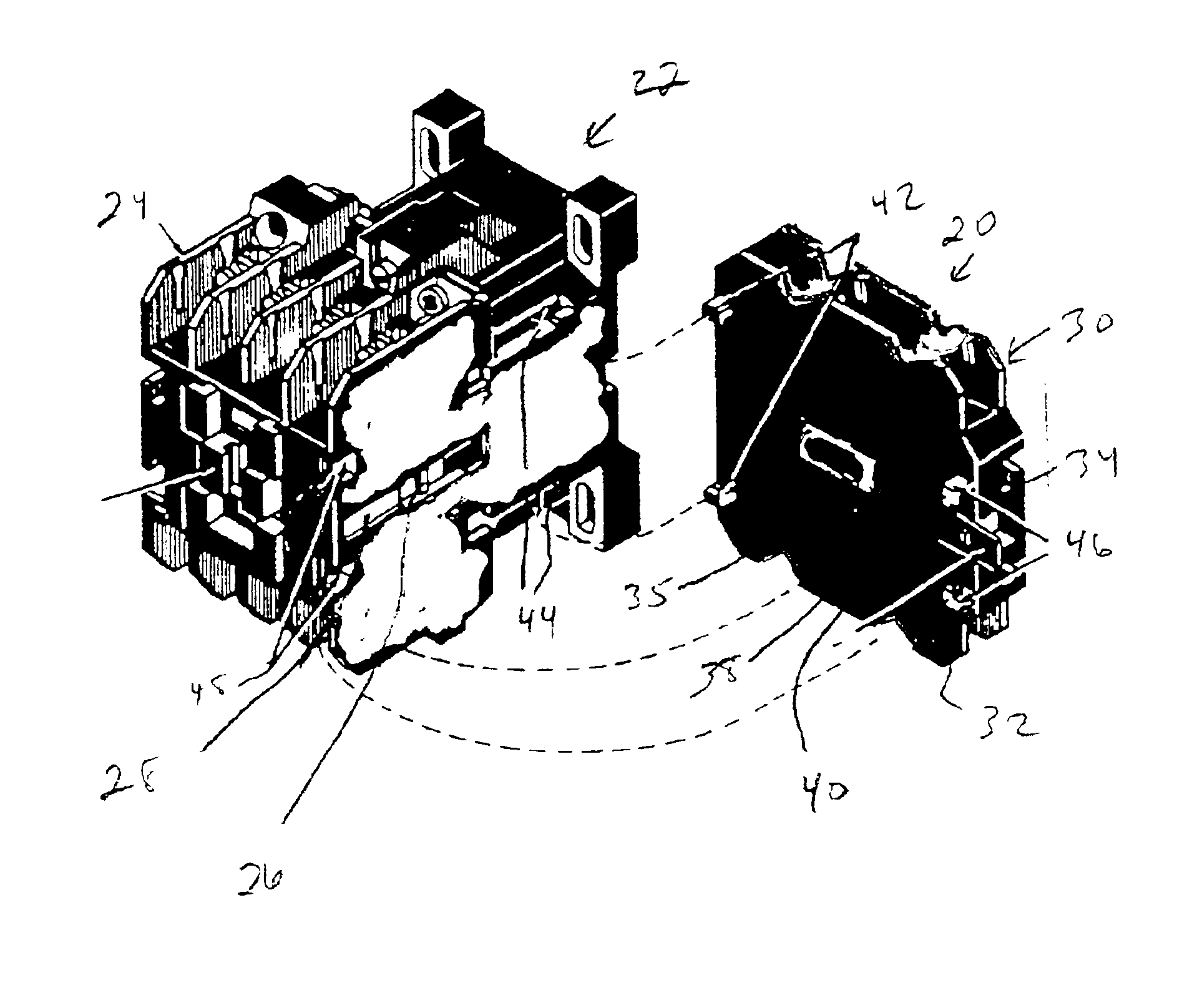
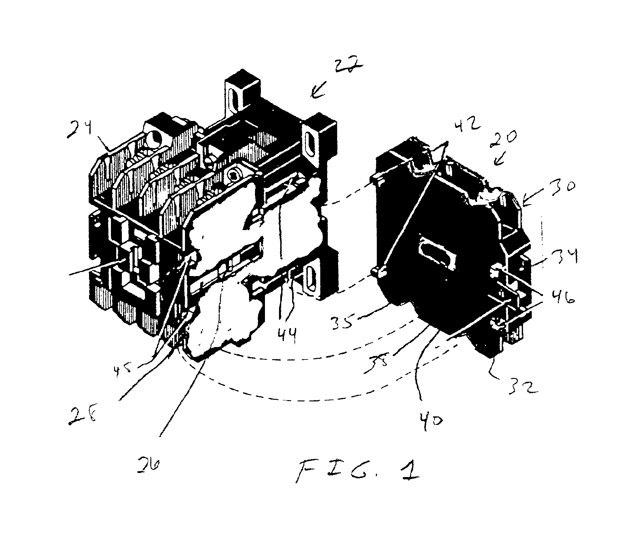
Referring to FIG. 1, a contact assembly in the form of an auxiliary contact block 20 for use with an electrical switching apparatus in the form of an electrical contactor 22 is illustrated. The electrical contactor 22 is of conventional construction and includes a housing 24 which may be of an insulating plastic. Although not specifically illustrated herein, the housing 24 encloses an electrical coil associated with a magnetic core and armature for driving an actuator 26 positioned in a side opening 28 of the housing 24. Additionally, the housing 24 encloses various electrical contacts which can be opened or closed responsive to energization of the coil.

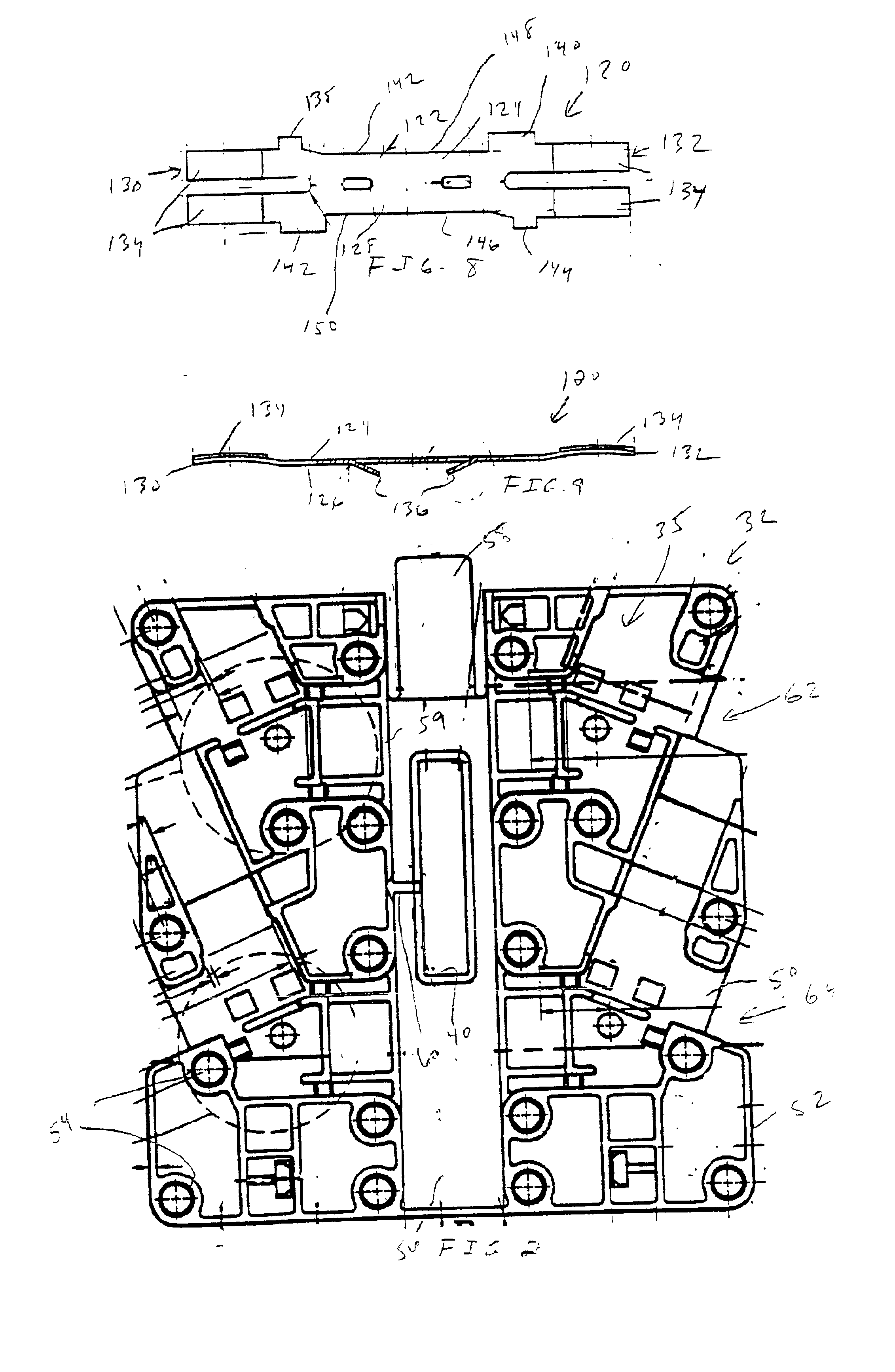
The auxiliary contact block 20 includes an enclosure 30. The enclosure 30 is formed of a housing 32 and cover 34 which are held together in a conventional manner to define an interior space 35. A plunger 36, see FIG. 3, in the interior space 35 includes a neck 38 extending through an opening 40 in the housing 32. The housing includes...


PUM


Abstract

A contact assembly for use in an electrical switching apparatus has an actuator. An enclosure comprises an interior space housing first and second stationary contacts fixedly mounted in spaced relation with one another in one of a normally closed position or a normally open position. A pusher is movably mounted in the enclosure and is selectively driven by the actuator to move between a normal position and an actuated position. The pusher comprises a top wall, a bottom wall and first and second side walls connected between the top wall and bottom wall to define an opening having respective first and second ends. First and second longitudinally spaced top ribs are on an inside of the top wall proximate the respective first and second side walls. First and second longitudinally spaced bottom ribs are in an inside of the bottom wall proximate the respective first and second side walls and laterally offset from the respective first and second top ribs. A movable contact is received in the opening. A contact spring is captured between the top rib and the bottom rib at either the first or the second end of the opening to bias the movable contact against the top rib and the bottom rib at the other of the first end and second end of the opening.

Description

TECHNICAL FIELD OF THE INVENTIONThis invention relates to a contact assembly for use in an electrical switching apparatus designed to minimize incorrect assembly.BACKGROUND OF THE INVENTIONA conventional electrical switching apparatus in one form typically comprises an electromagnetically actuated device having a magnetic core proximate an armature. Typically, a coil is electrically energized to draw the armature to the magnetic core. The electromagnetically actuated device may be a control relay, a contactor, a motor starter or the like. The armature is operatively associated with a movable device such as an actuator. With an electrical switching apparatus the actuator operates a contact assembly.A contact assembly may be an integral component of the electrical switching apparatus or it may be an auxiliary device to be added thereto. In either case, the contact assembly typically includes a contact having a pair of stationary contacts and a movable contact. In one known form of a c...

Claims


Application Information

Patent Timeline
Patent Type & Authority Patents(United States)
IPC IPC(8): H01H50/54
CPCH01H50/541H01H2300/042H01H2050/046H01H50/546
Inventor PASSOW, CHRISTIAN H.TEWS, KEVIN B.
Owner SIEMENS IND INC
Why Eureka
Try Eureka