Throttle body to intake manifold mounting

a technology of intake manifold and throttle body, which is applied in the direction of combustion air/fuel air treatment, machines/engines, manufacturing tools, etc., can solve the problems of eddies being formed, affecting the maximum amount of flow to the engine, and whistling sound that is noticeable to the operator of the vehicl

Active Publication Date: 2013-06-18
FORD GLOBAL TECH LLC
View PDF8 Cites 8 Cited by
  • Summary
  • Abstract
  • Description
  • Claims
  • Application Information

AI Technical Summary

Benefits of technology

[0006]According to an embodiment of the disclosure at least two sets of locator pins are provided on the flange of the intake manifold which couple with orifices provided on the flange of the throttle body. In addition, through holes are provided on the throttle body flange and threaded inserts are provided on the flange of the intake manifold. The locator pins are coupled with the orifices prior to inserting a bolt through the through holes to engage with the threads of the threaded insert. By providing the locator pins, the two flanges are held in a desired orientation so that the ducts of the two flanges are properly aligned to substantially eliminate a step at the interface.
[0007]In one embodiment, a throttle body-to-manifold coupling system has a first flange coupled to the throttle body, a second flange coupled to the manifold, a set of locator pins extending outwardly from the second flange, and an orifice provided on the first flange for the set of locator pins. The set of locator pins and the associated orifice are arranged to couple when the manifold is assembled to the throttle body. An inside diameter of the first flange is substantially equal to an inside diameter of the second flange. The second flange further comprises at least three threaded inserts arranged on the periphery of the second flange. The first flange has a through hole associated with each of the at least three threaded inserts. A bolt associated with each of the at least three threaded inserts is inserted through the through hole and engaged with threads on the threaded insert. The locator pins extend outwardly from the second flange approximately perpendicular to a face of the second flange. A cross section of each set of locator pins in a plane parallel to a face of the flange is contained within a cylinder having a diameter substantially equal to a diameter of the orifice. The intake manifold, the flange of the intake manifold, and the locator pins are comprised of a polymeric, elastic material. In one embodiment, the set of locator pins is arranged on the flange along an axis roughly perpendicular to the axis of the pin associated with the throttle valve. This location locates the intake manifold with respect to the throttle body in the area in which a mismatch or step is more problematic. In other embodiments, two or more sets of locator pins with associated orifices are provided. In such an embodiment, the sets of locator pins may be place around the flange asymmetrically to prevent misassembly.
[0009]By using a set of locator pins of an elastic material, the pins can flex to facilitate the alignment and coupling of the pins with the orifices. Also, the chamfers assist in the alignment. As the locator pins are fully engaged with the orifices, however, the pins provide little or no flexibility in alignment and force the throttle body into proper alignment with the intake manifold. Such a system provides an advantage over coupling systems relying solely on the through holes in the throttle body for alignment.
[0011]Not only do the locator pins align the central openings in the two flanges, but they also aid in the assembly of the intake manifold with the throttle body by holding the two together while the bolts are inserted and tightened.

Problems solved by technology

The mismatch leads to eddies being formed and leads to a whistling sound that is noticeable to the operator of the vehicle.
Such a mismatch also slightly negatively impacts the maximum amount of flow to the engine, i.e., slightly hurting peak engine performance.
The mismatch shown in FIG. 1 is particularly troublesome because it is located proximate the flow when throttle valve 11 is partially open.
Thus, a mismatch occurring in the vicinity of where the majority of the flow enters is particularly troublesome.
As the locator pins are fully engaged with the orifices, however, the pins provide little or no flexibility in alignment and force the throttle body into proper alignment with the intake manifold.

Method used


Image

  • Throttle body to intake manifold mounting
  • Throttle body to intake manifold mounting
  • Throttle body to intake manifold mounting

Examples


Embodiment Construction

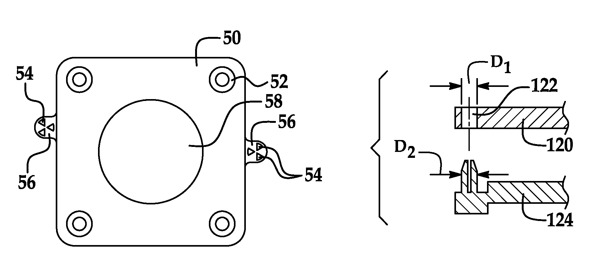
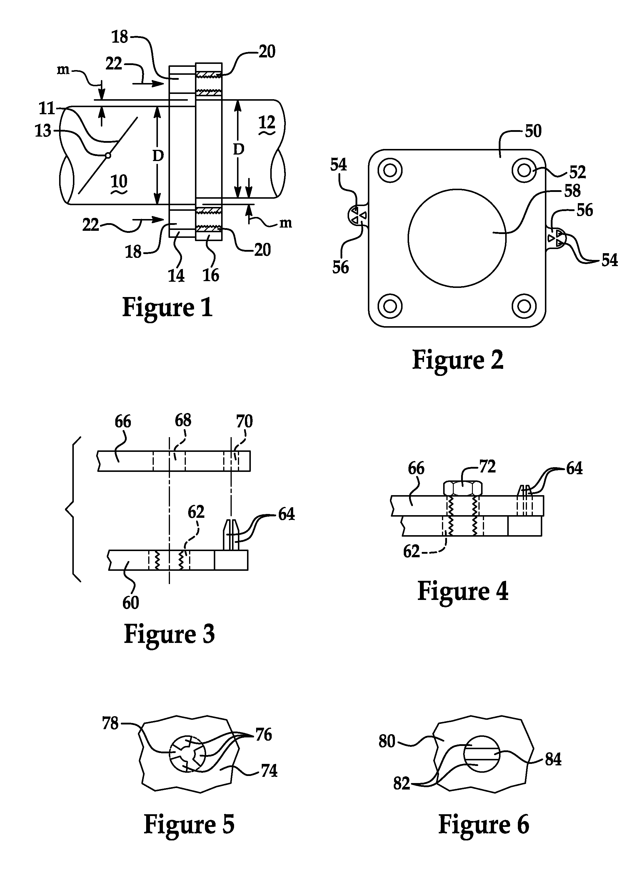
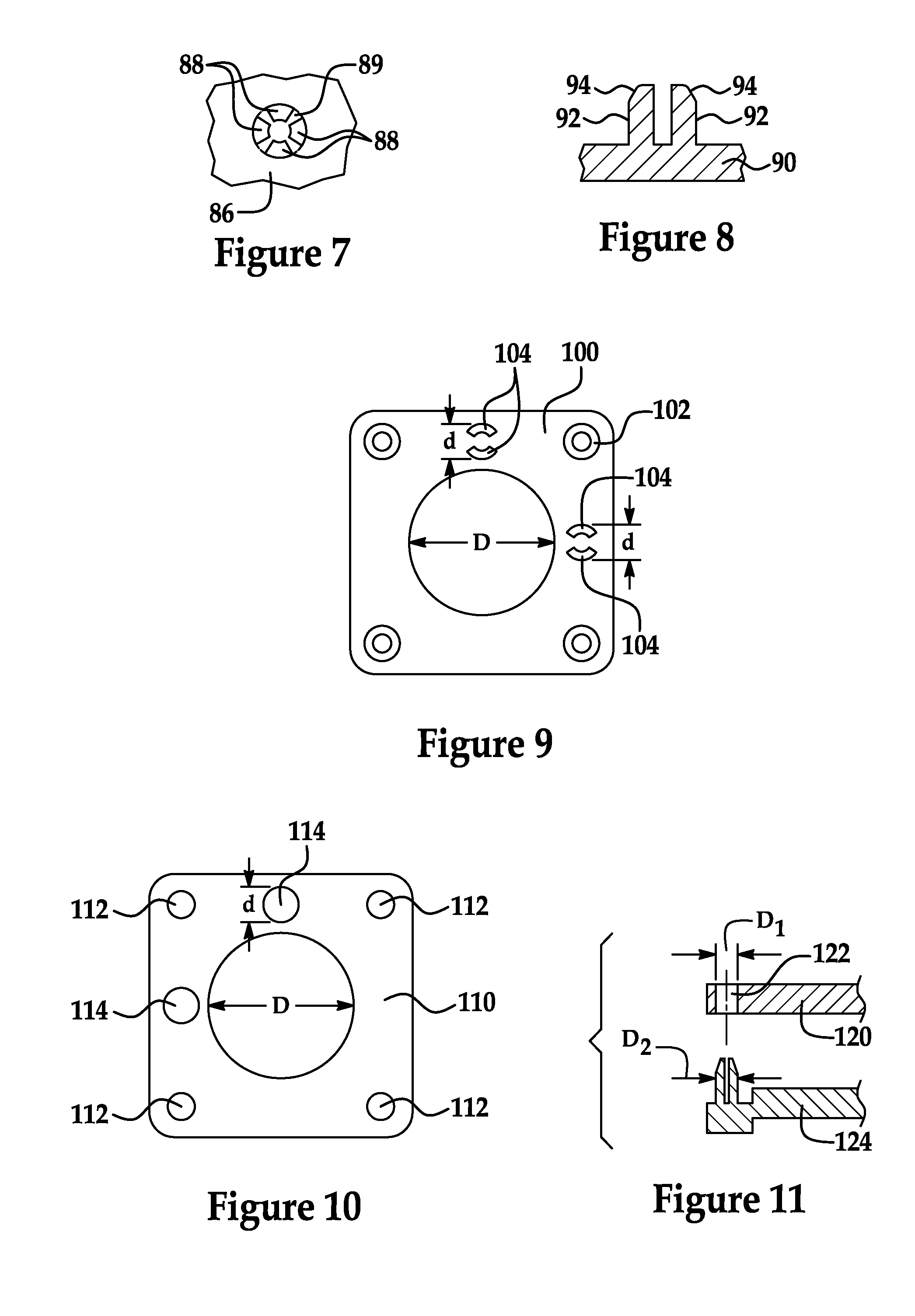
[0021]As those of ordinary skill in the art will understand, various features of the embodiments illustrated and described with reference to any one of the Figures may be combined with features illustrated in one or more other Figures to produce alternative embodiments that are not explicitly illustrated or described. The combinations of features illustrated provide representative embodiments for typical applications. However, various combinations and modifications of the features consistent with the teachings of the present disclosure may be desired for particular applications or implementations. Those of ordinary skill in the art may recognize similar applications or implementations consistent with the present disclosure, e.g., ones in which components are arranged in a slightly different order than shown in the embodiments in the Figures. Those of ordinary skill in the art will recognize that the teachings of the present disclosure may be applied to other applications or implemen...


PUM

PropertyMeasurementUnit
diameteraaaaaaaaaa
lengthaaaaaaaaaa
clamping forceaaaaaaaaaa

Abstract

At least one set of locator pins is provided on the flange of an intake manifold which couple with an orifice provided on the flange of a throttle body to align the two parts to ensure that they are properly oriented when assembled. In addition, through holes are provided on the throttle body flange and threaded inserts are provided on the flange of the intake manifold. The locator pins are coupled with the orifices prior to inserting a bolt through the through holes to engage with the threads of the threaded insert. By providing the locator pins, the two flanges are held in a desired orientation so that the ducts of the two flanges are properly aligned to substantially eliminate a step or mismatch at the interface.

Description

BACKGROUND[0001]1. Technical Field[0002]The present disclosure relates to coupling a throttle body with an intake manifold.[0003]2. Background Art[0004]Automotive throttle bodies have a flange for coupling with a flange located on an inlet side of an intake manifold. Typically the throttle body is metallic, possibly of aluminum, with a metallic throttle plate pivoting inside. Modern intake manifolds are injection molded of a polymeric material. The coupling between the two are shown in FIG. 1. A cross-section of a portion of throttle body 10 is shown in FIG. 1. The throttle body has a throttle plate 11 that rotates about rod 13. Throttle plate 11 may be mechanically actuated by the operator of the vehicle. More commonly found recently, is an electronically actuated throttle plate that is actuated by a stepper motor (not shown) or other suitable motor. Throttle plate 11 includes a flange 14 that couples with a flange 16 of an intake manifold (a portion of a cross-section of which is ...

Claims


Application Information

Patent Timeline
Patent Type & Authority Patents(United States)
IPC IPC(8): F02D9/10
CPCF02M35/10085F02M35/10144Y10T29/53
Inventor BORN, DAVIDCHURCH, JEREMY WALTER
Owner FORD GLOBAL TECH LLC
Why Eureka
Try Eureka