System and method for automated focus measuring of a lithography tool

Inactive Publication Date: 2005-04-26
ASML HLDG NV
View PDF14 Cites 13 Cited by
  • Summary
  • Abstract
  • Description
  • Claims
  • Application Information

AI Technical Summary

Benefits of technology

[0010]Advantages of the above embodiments are they only require one or more repeat exposures, and then the wafer alignment system of an exposure tool is used to measure the patterned structure or structures as opposed to a human or external equipment. No external measurement is required and opportunity for human error is eliminated. This saves both time and money.
[0011]Another advantage of at least some of the embodiments is that the patterns are printed at a tilt with respect to a wafer, which allows

Problems solved by technology

This saves both

Method used


Image

  • System and method for automated focus measuring of a lithography tool
  • System and method for automated focus measuring of a lithography tool
  • System and method for automated focus measuring of a lithography tool

Examples


Embodiment Construction

Overview

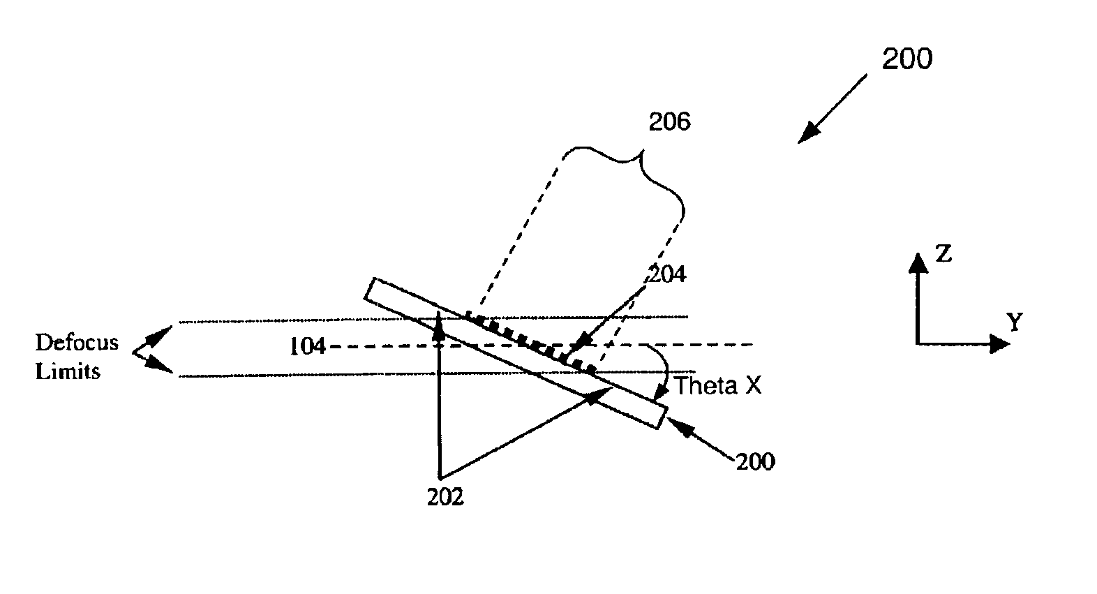
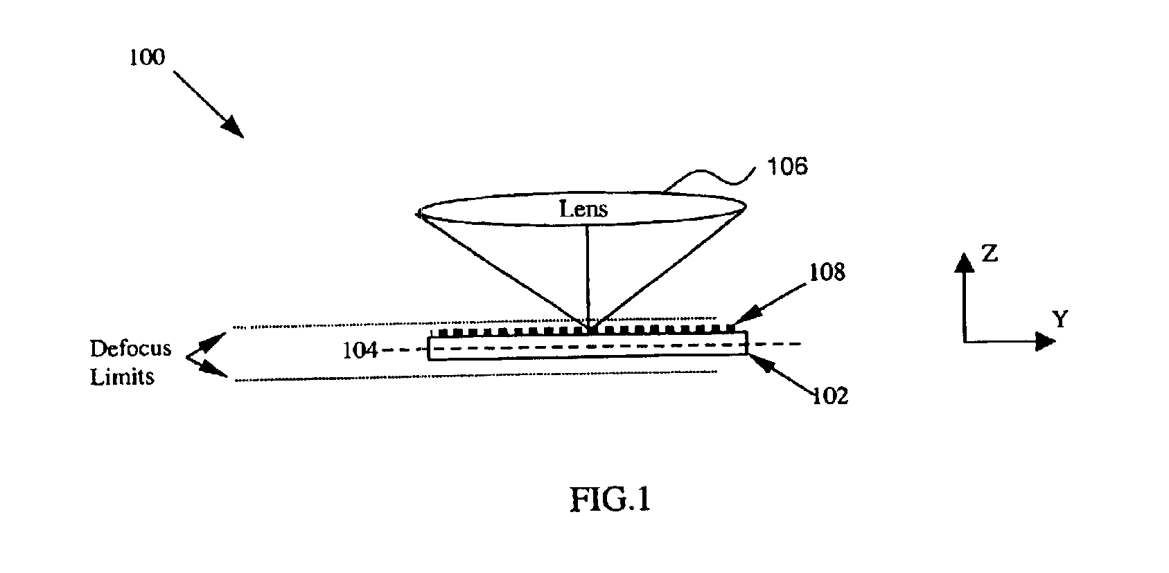
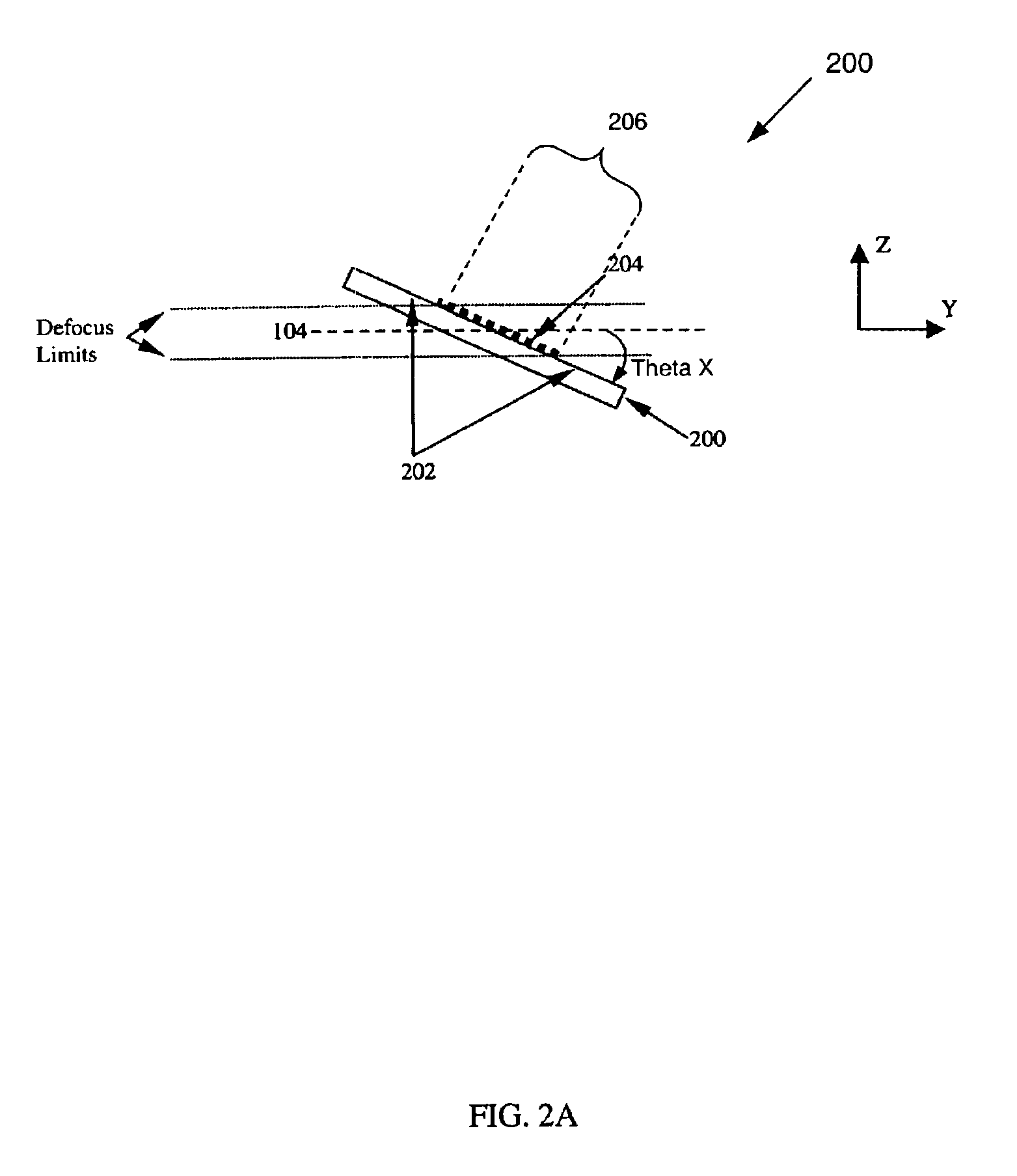
[0036]According to the present invention, a reticle is populated with identical structures possessing a critical dimension (CD) near a resolution capability of a stepper being used. The structures are densely spaced, covering the entire exposure field. The reticle is exposed such that the image formed by the exposure tool's projection optics is tilted with respect to a wafer. The result of exposing the reticle image onto a tilted wafer is that only a portion of the reticle image will resolve upon the wafer within the usable depth of focus (UDOF) of the exposure tool. Within the UDOF, the structures will print in the photoresist. However, the structures falling outside the UDOF will not adequately resolve and the incident light will be adequate to clear away all of the photoresist. After proceeding through a develop process, a visible band of patterned photoresist will remain on the wafer.

[0037]When resist properties and exposure conditions remain constant characteristics of ...


PUM


Abstract

A system and method are used to calibrate a focus portion of an exposure section of a lithography tool. A wafer is exposed so that a resulted or formed patterned image is tilted with respect to the wafer. The tilting can be imposed based on controlling a wafer stage to tilt the wafer or a reticle stage to tilt the reticle. The wafer is developed. Characteristics of the tilted patterned image are measured with a portion of the lithography tool to determine focus parameters of an exposure system. The portion can be an alignment system. The measuring step can measure band width and/or band location of the tilted patterned image. Sometimes, more than one patterned image is formed on the wafer, then the measuring step can measure distance between bands and shifting of the bands with respect to a central axis of the wafer. The focus parameters can be focus tilt errors and/or focus offset. The focus parameters are used to perform calibration. Calibration is done by either automatically or manually entering compensation values for the measured focus parameters into the lithography tool.

Description

CROSS-REFERENCE TO RELATED APPLICATIONS[0001]This application claims priority under 35 U.S.C. § 119(e) to U.S. Provisional Appl. No. 60 / 391,931 filed Jun. 28, 2002, which is incorporated by reference herein in its entirety.BACKGROUND OF THE INVENTION[0002]1. Field of the Invention[0003]The present invention is directed to a system and method for automated measuring of a focus portion of an exposure section of a lithography tool.[0004]2. Background Art[0005]Lithography systems are routinely calibrated to ensure the exposure optics are focused properly on a wafer surface. This decreases fabrication of devices that do not comply with certain tolerances by reducing printing or imaging errors caused by focus offset or focus tilt errors. One method of calibrating focus optics involves using a focus test reticle with structures that are patterned into a layer of photoresist on a wafer. The patterned structures are then evaluated manually using a microscope and recorded data is input into a...

Claims


Application Information

Patent Timeline
IPC IPC(8): G01B11/00G03F7/20G03F7/207G03F7/22G03F9/00H01L21/027
CPCG01B11/00G03F7/70641G03F7/70516G03F7/20
Inventor LYONS, JOSEPH H.WHELAN, JOSEPH G.
Owner ASML HLDG NV
Why Eureka
Try Eureka