Technology of high polymer material post-grouting squeezed cast-in-place pile

A high-polymer, post-grouting technology, applied in sheet pile wall, construction, infrastructure engineering, etc., can solve the problem that the grouting pipe is easy to be coagulated by the cement slurry, the shape and character are not easy to control, and the grouting effect is affected by the properties, etc. It can achieve the effect of avoiding the extrusion and expansion of mechanical equipment construction technology, which is conducive to environmental protection and energy saving, and avoids collapse of holes and excessive soil at the pile end.

Active Publication Date: 2012-07-18
HOHAI UNIV
View PDF14 Cites 32 Cited by
  • Summary
  • Abstract
  • Description
  • Claims
  • Application Information

AI Technical Summary

Problems solved by technology

This process simplifies the process of bottom expansion at the pile end, but the shape of the base of the expansion head is greatly affected by the age of the cement slurry; after the high-pressure grouting is completed, there is a certain degree of uncertainty in the formation of the base slurry under the surrounding pressure
In addition, these construction methods can improve the characteristics of the pile-soil contact surface to varying degrees, increase the pile side and pile end resistance, and improve the overall bearing capacity of the pile foundation; however, these technical solutions all use cement grout for grouting, so the grouting strength, The grouting effect such as the grouting pressure and the improvement of the bearing capacity of the pile foundation are limited by the cement slurry; when the thick grout is poured for a long time, there are problems such as the grouting pipe is easily blocked by the cement slurry in the hole
In the traditional post-grouting cast-in-situ pile technology, the grouting effect is greatly affected by the properties of the pile side soil, and the shape and properties after grouting are not easy to control

Method used


Image

  • Technology of high polymer material post-grouting squeezed cast-in-place pile
  • Technology of high polymer material post-grouting squeezed cast-in-place pile
  • Technology of high polymer material post-grouting squeezed cast-in-place pile

Examples


Embodiment Construction

[0021] Specific embodiments of the present invention will be described in detail below in conjunction with the accompanying drawings. The protection scope of the present invention is not limited only to the description of this embodiment.

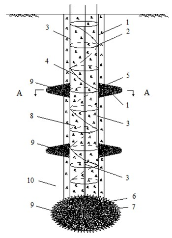
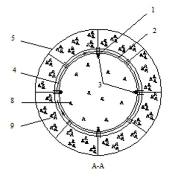
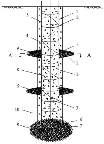
[0022] like figure 1 and figure 2As shown, during implementation, firstly, the pile driver is in place, the hole is dug by the conventional bored pile forming process, and the mud wall is used to protect the wall. The diameter of the pile body is 300-1000 mm, and the depth is 10-35 m; assemble the reinforcement cage The main reinforcement 1 and reinforcement 2, and the rigid grouting pipe 3 is bound inside the main reinforcement 1 of the steel cage, and the flexible grouting pipe 4 with grouting holes is wound spirally on the outside of the main reinforcement 1 and reinforcement 2 of the reinforcement cage along the depth direction of the reinforcement cage The rigid grouting pipe 3 is a steel pipe with an outer diameter of 10-25 mm and ...


PUM


Abstract

Disclosed is construction technology of high polymer material post-grouting squeezed cast-in-place pile. The technology includes that a conventional bored pile is adopted for forming a hole, a grout filling bag is arranged on a reinforcement cage with a designed depth, the reinforcement cage sinks, concrete is cast, high polymer materials are in pressure grouting for the filling bag at a designed position by the aid of a grouting line after the pile building concrete is initially set, and a high polymer material post-grouting squeezed branch and an expanded-base grouting pile are formed. Construction process of a squeezed branch pile and technology of a post-grouting cast-in-place pile are optimized by a method, and problems of squeezing hole collapse of a traditional squeeze branch pipe, excessive scum at a pile end and the like are avoided. In addition, a large quantity of expenditure and construction period can be saved, the high polymer grouting technology is favorable for environmental protection and energy economization, and the quality is easy to control. Besides, the method is simple in construction process, high in operability, convenient in quality control, and remarkable in economic benefit and the effect of management of a soft soil foundation.

Description

technical field [0001] The invention relates to the technical field of pile foundations, in particular to a high polymer material post-grouting extruded and expanded cast-in-place pile technology. It is mainly suitable for engineering and technical fields such as foundation treatment of industrial and civil buildings and soft soil foundation treatment such as coastal and riverside highways and railways. [0002] Background technique [0003] The bearing capacity of pile foundation is mainly composed of pile side friction resistance and pile tip resistance. Changing the section form of longitudinal pile body and optimizing the mechanical properties of pile-soil contact surface have become one of the important means to improve the bearing capacity performance of cast-in-place piles. Post-grouting cast-in-place piles, by embedding grouting pipes in the cast pile body, joint grouting on the pile side, pile end or pile side pile ends to improve pile side friction and pile end re...

Claims


Application Information

Patent Timeline
Patent Type & Authority Applications(China)
IPC IPC(8): E02D5/48E02D5/36E02D15/04
Inventor 孔纲强周航曹兆虎陈力恺
Owner HOHAI UNIV
Why Eureka
Try Eureka