System and method of operation of dual redundant controllers

a controller and dual-replacement technology, applied in the field of computer systems, can solve problems such as system reflection

Inactive Publication Date: 2005-01-18
CISCO SYST CANADA
View PDF29 Cites 59 Cited by
  • Summary
  • Abstract
  • Description
  • Claims
  • Application Information

AI Technical Summary

Problems solved by technology

It is also often the case where critical systems are located in remote, difficult to access or hazardous locations.
The systems therefore do not reflect the functionality associated with rack based computer systems where redundant controllers may be located on separate boards that are likely to be removed during the operation of the computer.

Method used


Image

  • System and method of operation of dual redundant controllers
  • System and method of operation of dual redundant controllers
  • System and method of operation of dual redundant controllers

Examples


Embodiment Construction

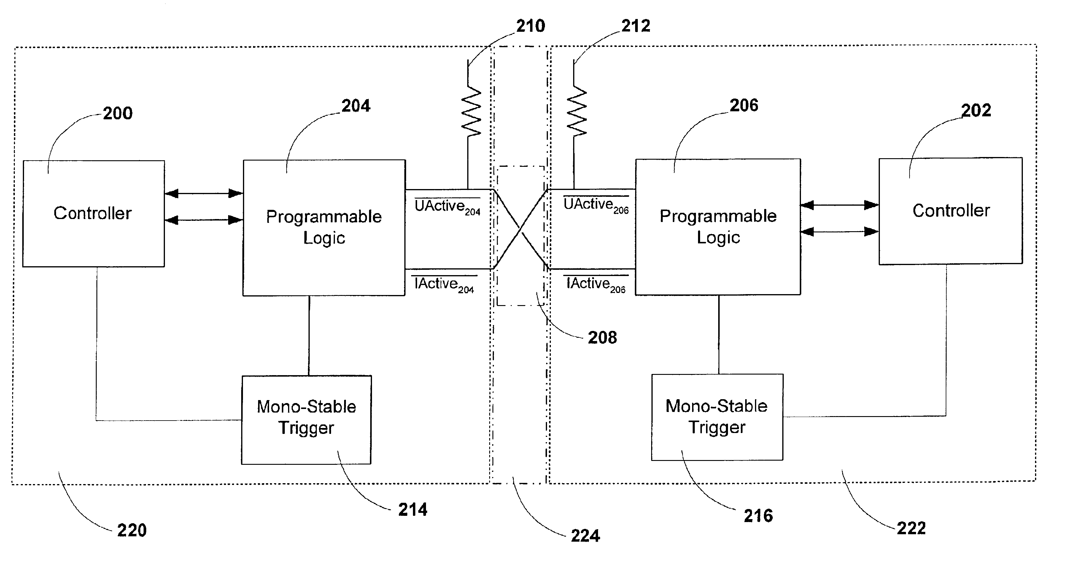
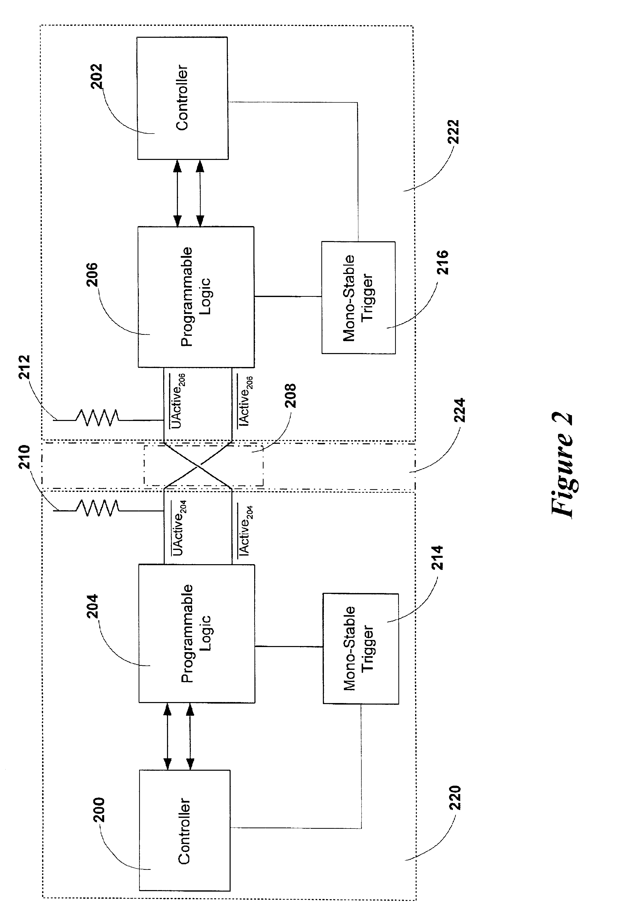
The invention provides a system and method for monitoring and switching control between dual redundant controllers. The invention is suitable for use in an industrial computer where an industrial computer is a computer that comprises a passive plane. This passive plane is appropriate for the acceptance of one or more peripheral boards where the peripheral boards provide the desired functionality to the industrial computer.

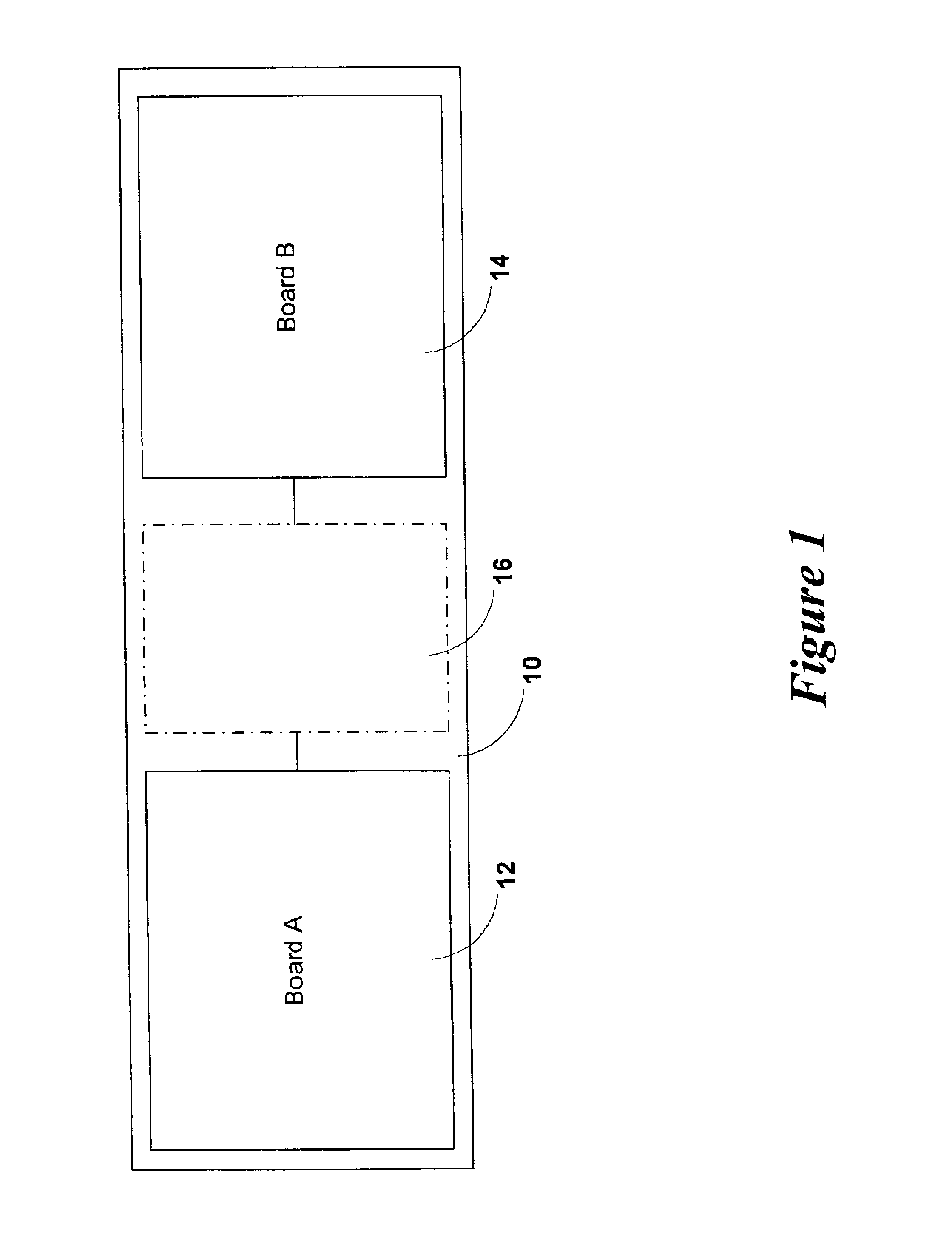
A schematic diagram of portions of an industrial computer that contains the system of an embodiment of the invention is illustrated in FIG. 1. Industrial computer 10 contains boards 12 and 14. Boards 12 and 14 are inserted in and connected to passive plane 16 of industrial computer 10. Passive plane 16 generally provides for communications within the industrial computer and particularly provides for communications between boards 12 and 14. Boards 12 and 14 each contain a controller which form a pair of redundant controllers. The active controller of the pair of red...


PUM


Abstract

A system and method for the switching of control between redundant controllers is presented. The status of the redundant controllers is monitored to determine if switching of control between controllers is required. The monitoring and switching system is hardware based with control being implemented via a state machine.

Description

FIELD OF THE INVENTIONThe invention relates generally to computer systems, and more particularly to a system and method of improving the reliability of a computer system through the implementation of a redundant controllers.BACKGROUND OF THE INVENTIONThe provision of redundant systems in areas where uninterrupted operation is required are well known. Such uninterrupted operations may be desired for any combination of economic and safety considerations. Redundant control systems are found in many industrial settings including; chemical plants and utility power systems. Redundant control systems are also employed in real time computer and communications systems as might by used in on-line data processing systems as are used in banking and telephone switching, for example. It is also often the case where critical systems are located in remote, difficult to access or hazardous locations. In such cases the provision of redundancy not only allows for improved operational reliability but a...

Claims


Application Information

Patent Timeline
Patent Type & Authority Patents(United States)
IPC IPC(8): G06F11/00G05B19/042G06F11/20
CPCG05B19/0428G06F11/2038G06F11/20G06F11/2028G05B2219/24177G05B2219/24183
Inventor DITNER, JOHNMORIN, MARC
Owner CISCO SYST CANADA
Why Eureka
Try Eureka