Retractable tether for animals

Inactive Publication Date: 2005-01-25
ANDERSON PAUL G
View PDF52 Cites 59 Cited by
  • Summary
  • Abstract
  • Description
  • Claims
  • Application Information

AI Technical Summary

Benefits of technology

to provide a retractable leash having a reduced lik

Problems solved by technology

Also, since most leashes are mounted to a collar around the animal's throat, when the animal reaches the end of the cord, the cord can potentially cause discomfort or possible injury to the animal by pulling the collar sharply against the animal's throat.
Similarly, a large dog could potentially uproot

Method used


Image

  • Retractable tether for animals
  • Retractable tether for animals
  • Retractable tether for animals

Examples


Example

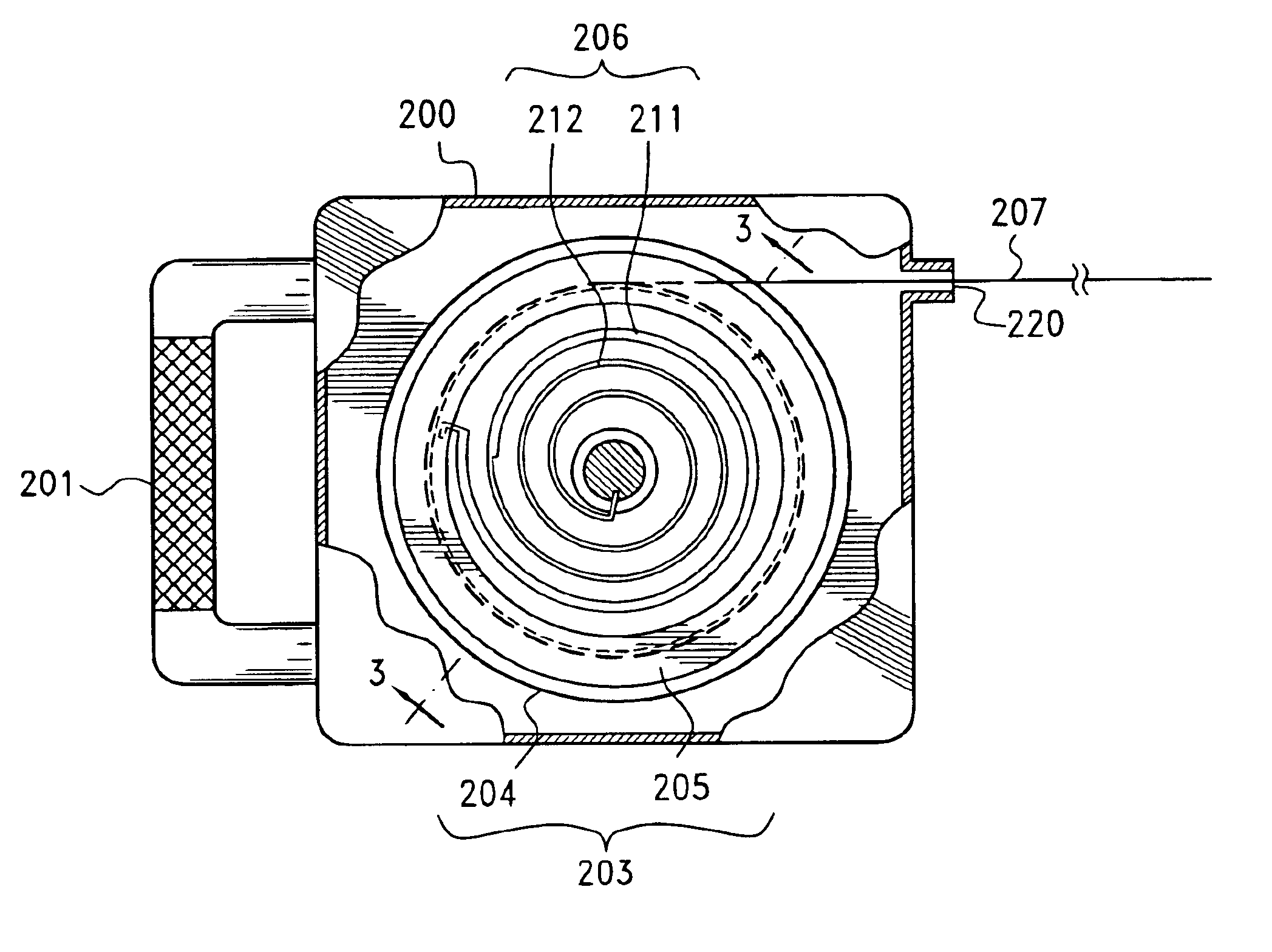
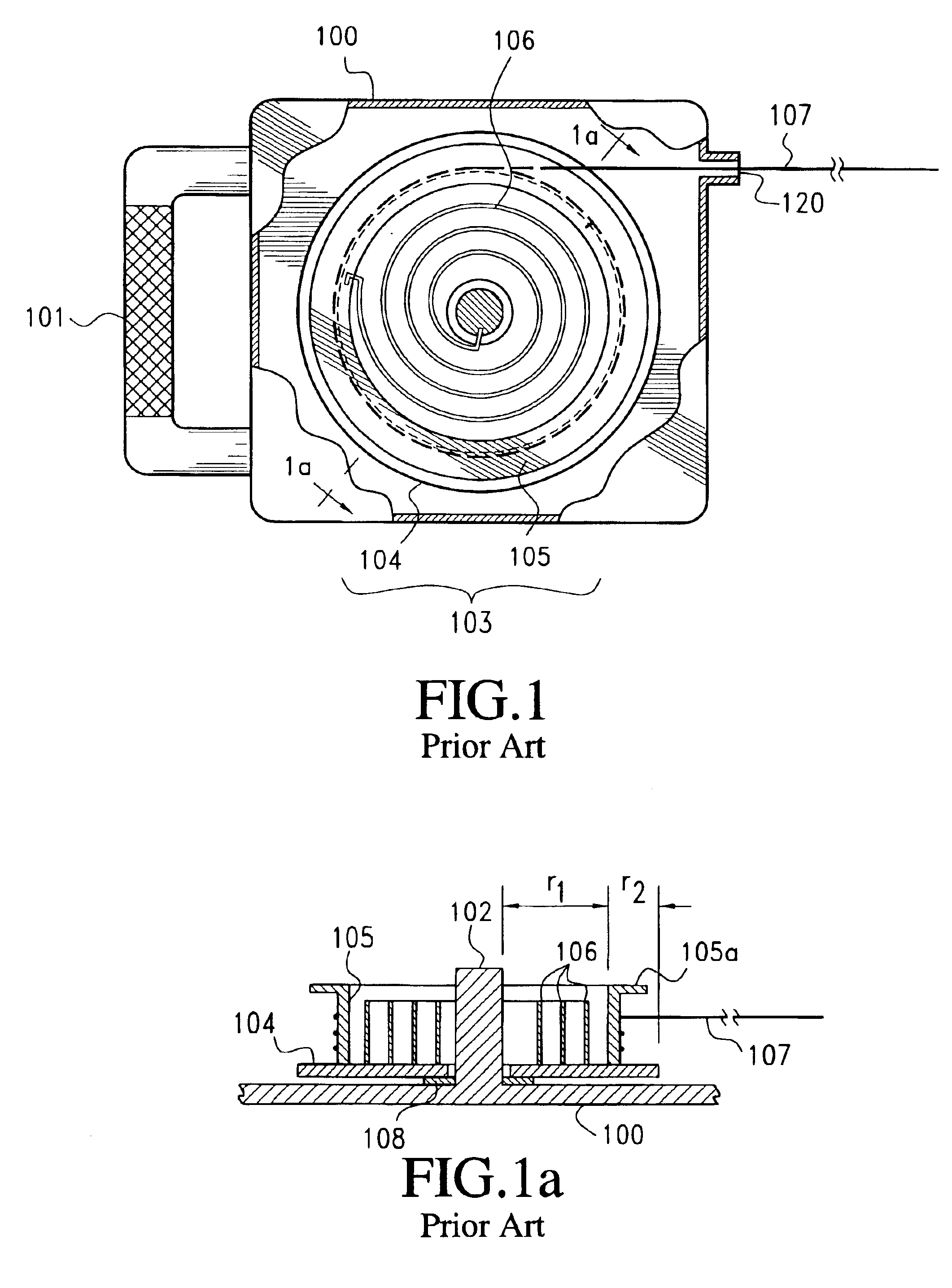
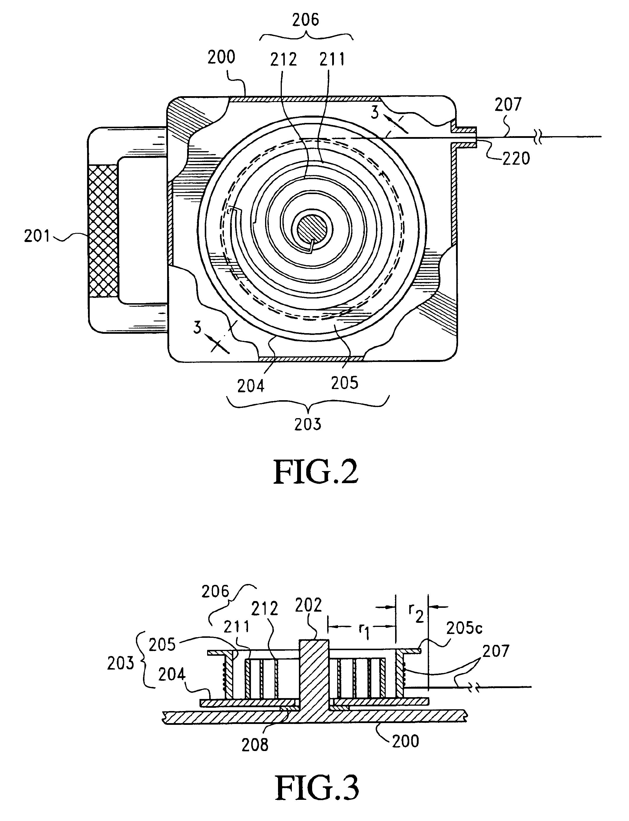
A retractable pet leash according to the prior art is shown in FIGS. 1 and 1a. The pet leash assembly comprises a housing 100 with a handle 101. Housing 100 has a top, a bottom, and a peripheral wall, with an opening 120 through the peripheral wall. Within the housing is an axle 102, which is rigidly mounted to the bottom of the housing. A spool 103 is rotatably mounted on the axle 102. For ease of rotation, the spool may be isolated from the bottom surface of the housing by a washer 108 made of a low-friction material. Suitable low-friction materials include a metal washer with a coating of grease or oil, or a washer formed of a low surface energy polymer, such as polytetrafluoroethylene. The spool 103 includes a disc 104 having a hole therethrough. Axle 102 passes through the hole in the disc 104, allowing the disc to rotate freely around the axle. A cylindrical wall 105 having an inner surface and an outer surface projects from disc 104 toward the top surface of the housing (FIG....


PUM


Abstract

A retractable animal tether, comprising a hand-held support; a spool rotatably mounted on the support; and a flexible cord wound on the spool, said flexible cord having an end which is connected to the spool and a second end which may be connected with the animal. The application of a first force F1 to a free end of the flexible cord causes a portion of the flexible cord to unwind from the spool. The tether also includes a means for preventing the remainder of the flexible cord from unwinding from the spool unless a second force F2 is applied to the free end of the flexible cord, said force F2 being greater than said force F1.

Description

FIELD OF THE INVENTIONThis invention is directed to an improved retractable tether for pets. Specifically, the invention provides a retractable animal tether having a flexible tether wound on a spool; and a mechanism providing variable resistance to rotation of the spool as an animal unwinds the tether from the spool. The tether may be a hand-held tether, such as a leash, or it may be mounted to a wall or to a horizontal surface, such as the ground or a floor.BACKGROUND OF THE INVENTIONRetractable leashes for dogs and other animals are very well known. They typically feature a housing containing a spool rotatably mounted on the axle. A flexible cord has a first end having a clip, which may be attached to a collar on an animal. A second end of the cord passes through an opening in the housing and connects rigidly to the spool. A spring causes the spool to preferentially rotate in a first direction so as to wind the cord onto the spool. When the spool rotates in a second direction so ...

Claims


Application Information

Patent Timeline
IPC IPC(8): A01K27/00B65H75/44B65H75/48
CPCB65H75/4431A01K27/004
Inventor ANDERSON, PAUL G.
Owner ANDERSON PAUL G
Why Eureka
Try Eureka