Eureka AIR delivers breakthrough ideas for toughest innovation challenges, trusted by R&D personnel around the world.

Aircraft canopy jettison apparatus with airbag

a technology of airbags and jettison apparatuses, which is applied in the direction of emergency apparatus, aircraft ejection means, seating arrangements, etc., can solve the problems of damage to the hearing of aircrews, delay in the timing of events and possible injury to aircrews, and the limitation of using a canopy thruster

Inactive Publication Date: 2005-01-25
THE UNITED STATES OF AMERICA AS REPRESENTED BY THE SECRETARY OF THE NAVY
View PDF14 Cites 10 Cited by
  • Summary
  • Abstract
  • Description
  • Claims
  • Application Information

AI Technical Summary

Benefits of technology

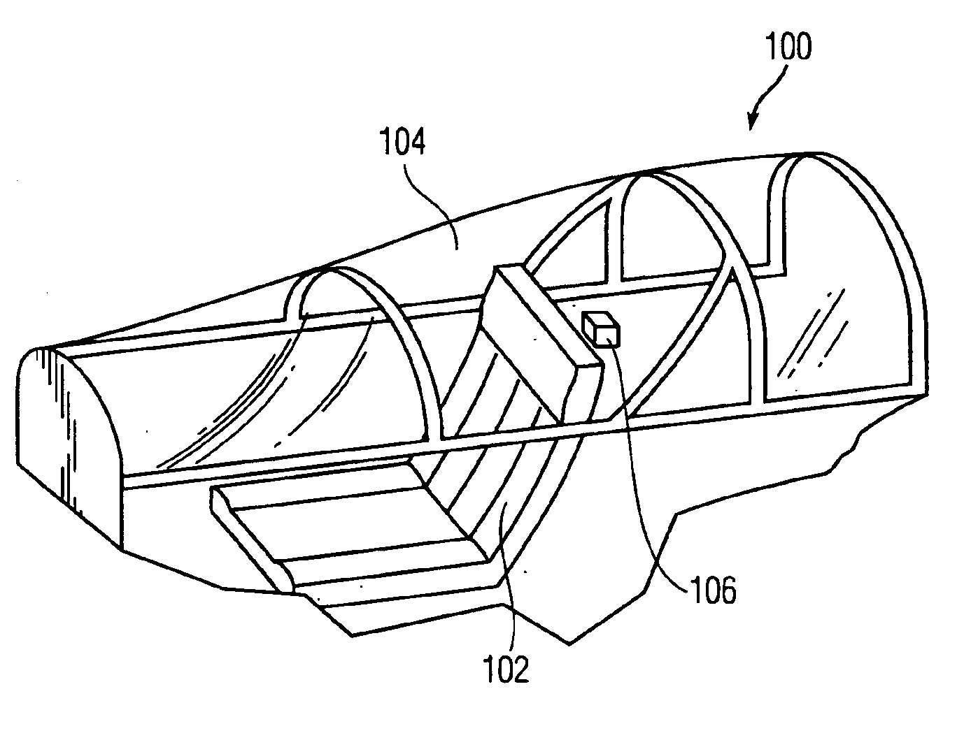
The present invention uses airbag technology to perform and / or assist in the work function of canopy removal for an aircraft during an emergency egress. In general, the airbag system comprises an inflatable airbag and a cartridge actuated device (CAD). The operation of the airbag starts by the initiation of the CAD. The CAD outputs gas that inflates the airbag. As the airbag begins to inflate, it forces the canopy open. Given the proper placement of the airbag, the distributed force applied to the canopy causes the canopy to be jettisoned from the aircraft. The airbag may be fixed to the airframe, canopy or ejection seat. The adaptability of an airbag system allows for an upgrade of existing aircraft's egress system; thereby serving to improve or solve escape path clearance related issues.

Problems solved by technology

Some of the limitations of using a canopy thruster have been seen over the past few years.
The failure of one part in the series of linkages can cause the canopy to remain attached to the aircraft or cause a delay in the timing of events and possible injury to the aircrew.
One problem with using rocket motors is the extreme amounts of noise generated, which can damage an aircrew's hearing.
Another problem with using rocket motors is the proximity of the rocket plume to the aircrew, which can cause serious injury to the aircrew.
One disadvantage of canopy fragilization is the use of explosives, in close proximity to the aircrew, to blow the transparent glass out of the canopy's metal frame.
One concern when using this method is the likelihood of fragments hitting the aircrew.
Another disadvantage is the noise that may be encountered due to the proximity of the aircrew to the explosive charge.

Method used


Image

  • Aircraft canopy jettison apparatus with airbag
  • Aircraft canopy jettison apparatus with airbag
  • Aircraft canopy jettison apparatus with airbag

Examples


Embodiment Construction

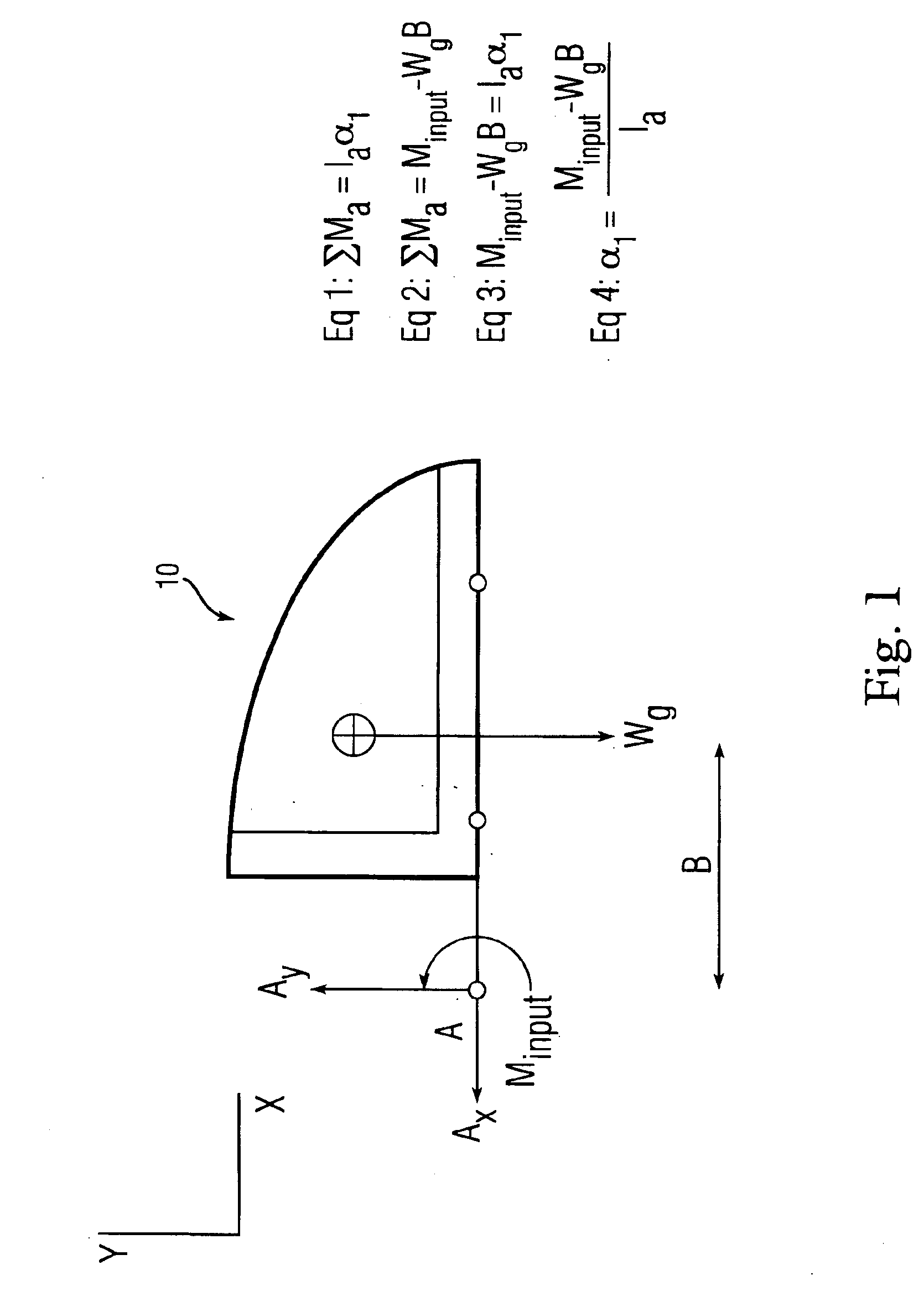
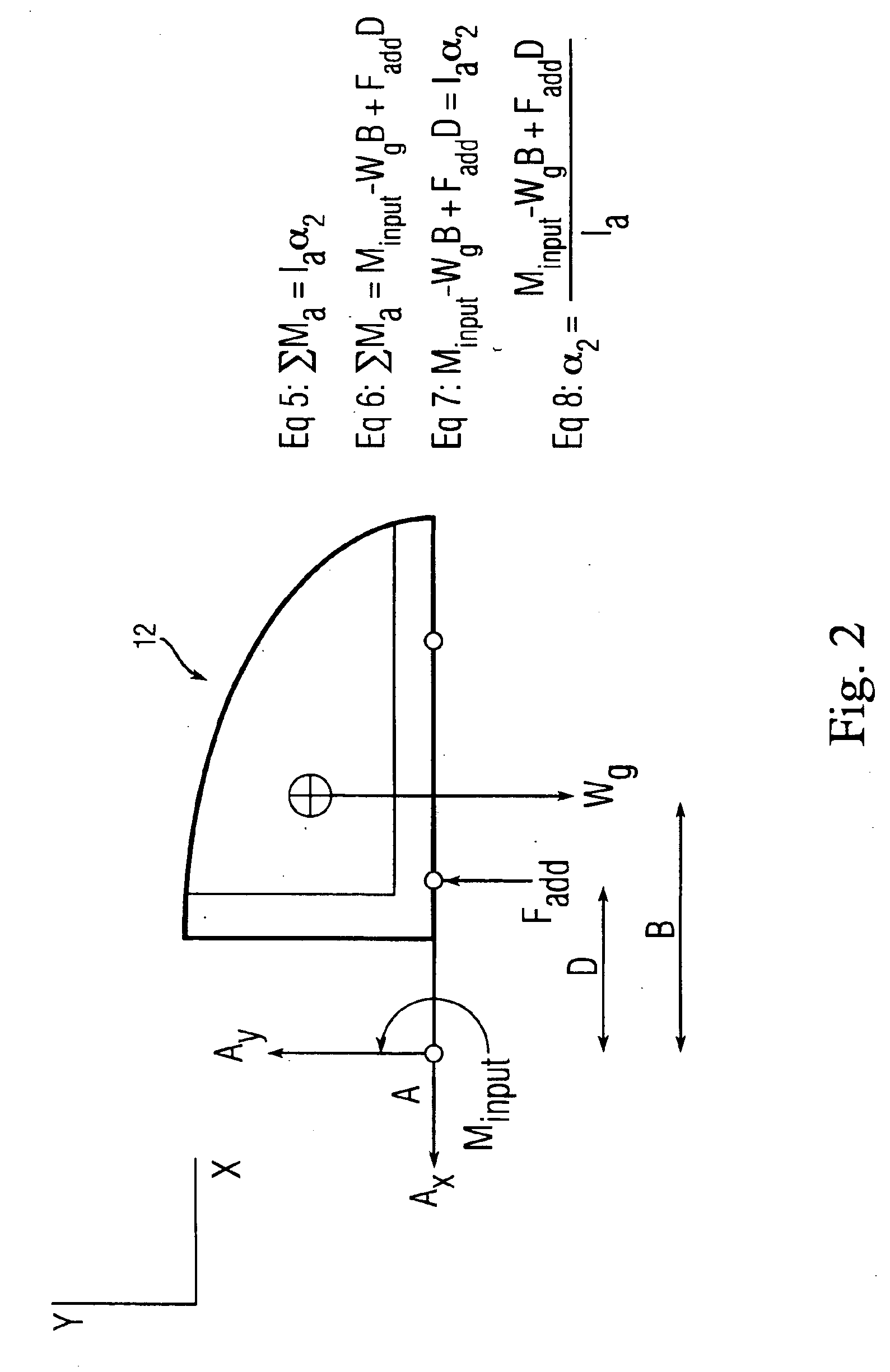
FIG. 1 is a force diagram of a canopy 10 without an airbag and FIG. 2 is a force diagram of a canopy 12 with an airbag. FIGS. 1 and 2 represent the difference between using an airbag (FIG. 2) as an additional force input to an existing canopy jettison system and one without the airbag (FIG. 1). The following analysis assumes that there is no air resistance and at the instant the canopy begins movement that Ax=0 and the angular velocity (w)=0. Equations 1 and 5 in FIGS. 1 and 2, respectively, are the equations for angular motion about a fixed point. Equations 1-4 relate to FIG. 1 and equations 5-8 relate to FIG. 2. The equations 1-8 are shown on the Figs. for clarity. The variables of the equations are:A: the axis of rotation point for the canopy.Ax: the reaction force in the positive x-direction. Units are (lbf) or (N)Ay: the reaction force in the positive y-direction. Units are (lbf) or (N)Minput: the initial momentum that is given to the canopy from a pre-existing canopy jettison ...


PUM


Abstract

A method of removing a canopy from a cockpit of an aircraft comprising providing an airbag in the cockpit adjacent the canopy; inflating the airbag; and as the airbag inflates, applying a force to the canopy from the inflating airbag to thereby jettison the canopy.

Description

BACKGROUND OF THE INVENTIONThe invention relates in general to aircraft canopy jettison apparatus and in particular to aircraft canopy jettison apparatus that include an airbag.There are three known ways to jettison an aircraft canopy during an emergency egress situation. The three ways are rocket motors, canopy thruster(s), and canopy fragilization. All three have advantages and disadvantages that dictate the effectiveness of a pilot's safe egress from an aircraft.Many older military aircraft still in service use a canopy thruster in combination with mechanical linkages to remove the canopy from an aircraft. Some of the limitations of using a canopy thruster have been seen over the past few years. Timing is a key factor to ensuring the successful egress of aircrew from an aircraft. The use of mechanical linkages to assist in the removal has a strong dependence on the resilience of these linkages. The failure of one part in the series of linkages can cause the canopy to remain attac...

Claims


Application Information

Patent Timeline
Patent Type & Authority Patents(United States)
IPC IPC(8): B64C1/00B64C1/32B64C1/14
CPCB64C1/1476B64C1/32B64D2201/00
Inventor REESE, JR., MILTON L.TERSINE, EDWARD G.
Owner THE UNITED STATES OF AMERICA AS REPRESENTED BY THE SECRETARY OF THE NAVY
Why Eureka
Eureka Blog
Learn More