Airbag and airbag device

a technology of airbags and airbags, which is applied in the direction of pedestrian/occupant safety arrangements, vehicular safety arrangments, vehicle components, etc., can solve the problems of large pressure loss, achieve easy adjustment, increase the capacity of the airbag, and reduce the effect of pressure loss during inflation and extension of the airbag

Inactive Publication Date: 2011-12-22
TAKATA CORPORATION
View PDF4 Cites 71 Cited by
  • Summary
  • Abstract
  • Description
  • Claims
  • Application Information

AI Technical Summary

Benefits of technology

[0026]According to the above-mentioned airbag and the airbag device of the present invention, by forming a projection portion on the airbag, a capacity of the airbag can be increased in a stepped manner, and an impact absorbing force can be effectively exerted. Also, by arranging the vent hole on the projection portion in an area where the airbag and the projection portion do not overlap each other, a discharge amount of the gas from the vent hole can be reduced by pulling the strap, and pressure loss during inflation and extension of the airbag can be reduced. Also, the gas discharged from the vent hole can be prevented from directly being injected to the surface of the airbag.
[0027]By configuring such that the vent hole is opened/closed by intensity of tension of the strap, the discharge amount of the gas from the vent hole can be easily adjusted, and the impact absorbing force of the airbag device can be adjusted according to the physical size of the occupant. Also, by configuring the vent hole by a cut-out portion formed in the pulling direction of the strap, it can be configured such that when the strap is pulled, the cut-out portion presses each other so as to close the vent hole, while if the strap is loosened, the cut-out portion is pushed open by the inflow gas in the projection portion so as to open the vent hole.
[0028]By configuring such that the projection portion is stood up by having the gas flow in from the airbag, the projection portion can be inflated and extende

Problems solved by technology

In the airbag device in which such a vent hole is formed, there has been a problem that pressure loss i

Method used


Image

  • Airbag and airbag device
  • Airbag and airbag device
  • Airbag and airbag device

Examples


first embodiment

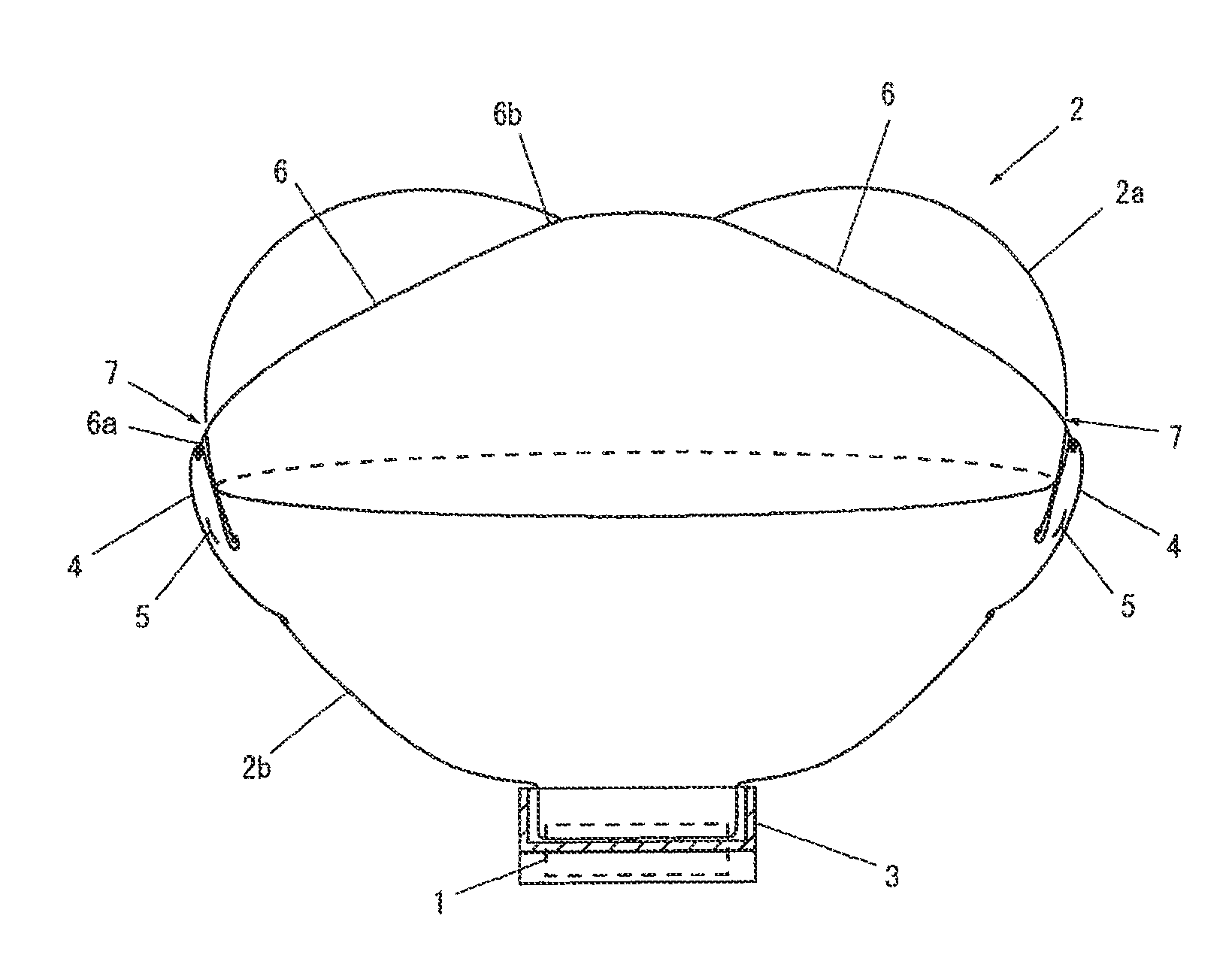
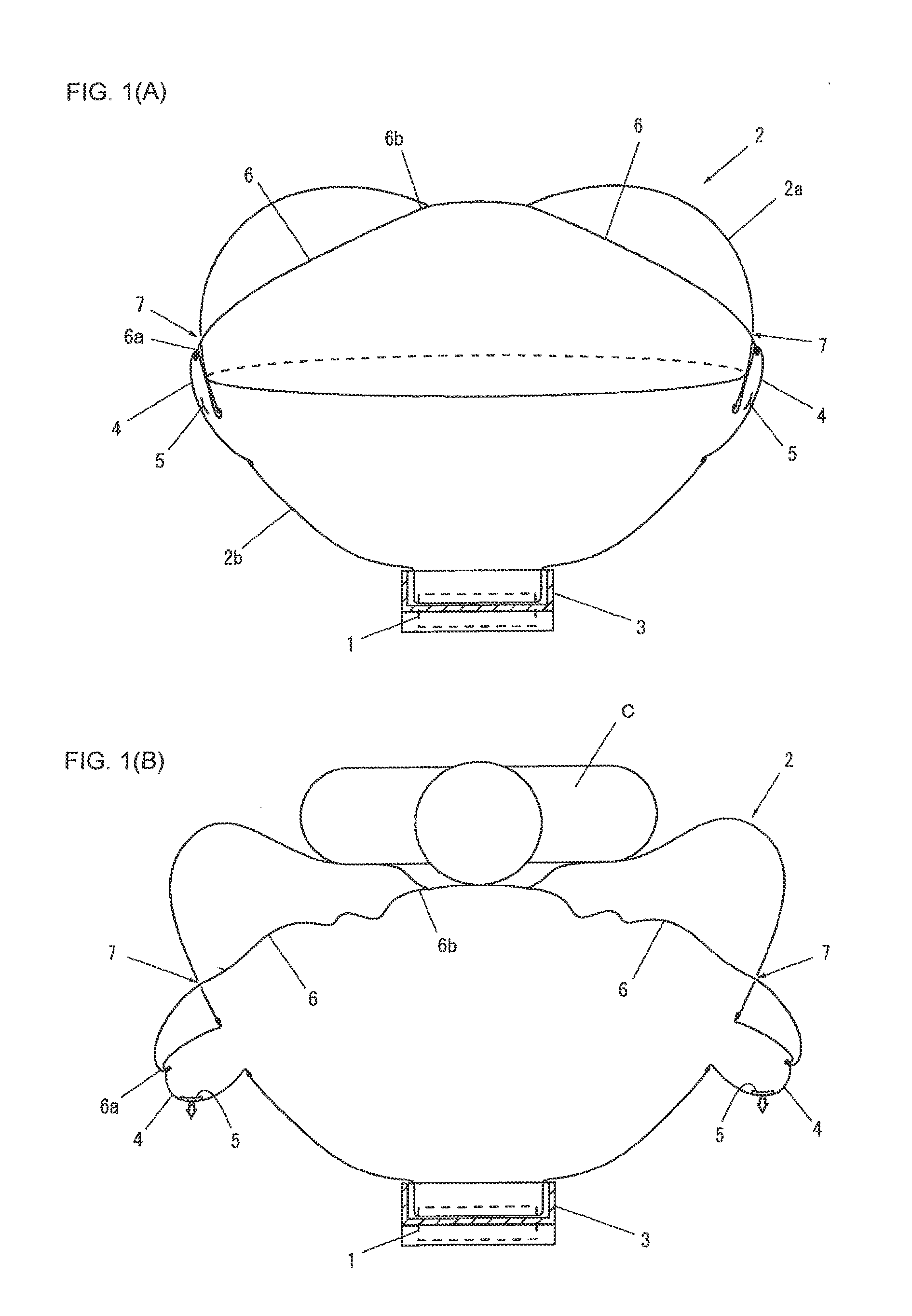
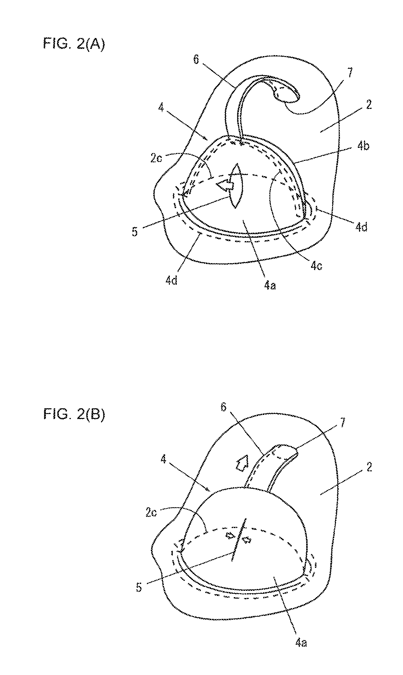
[0043]Subsequently, an action of the airbag device of the first embodiment will be described. As shown in FIG. 1(A), when the gas generator 1 is operated and the airbag 2 is inflated and extended, with movement of the top portion of the airbag 2, each strap 6 is brought into a pulled state. Then, the projection portion 4 is pulled by the tension of each strap 6 and maintains a crushed state and acts so as to close the vent hole 5. Therefore, leakage of the gas during inflation and extension of the airbag 2 can be reduced. Also, as shown in FIG. 1(B), when an occupant C touches the airbag 2, the top portion of the airbag 2 is moved to the retainer 3 side, by which each strap 6 is brought into a loose state, and the tension of the strap 6 is lowered. Also, at the same time, the gas flows into each of the projection portion 4 by pressure fluctuation caused by deformation of the airbag 2, and the internal pressure is raised. By means of these actions, each projection portion 4 stands up...

second embodiment

[0050]The second embodiment shown in FIG. 4 illustrates a case in which the other end 6b of the strap 6 is connected to a strap holding device 8 that can keep the length of the strap 6 constant and can release the strap 6. Since the strap holding device 8 is fixed to the retainer 3, it means that the strap 6 is connected to the retainer 3 through the strap holding device 8. Finally, the other end 6b of the strap 6 may be connected to the inner face of the airbag 2, as will be described later.

[0051]Here, a structure of the strap holding device 8 will be described referring to FIG. 5. FIGS. 5 are outline sectional views illustrating the strap holding device 8, in which (A) shows a pressurization type and (B) shows a piston type. The strap holding device 8 shown in FIGS. 5(A) and 5(B) is constituted by a cap 51 that can be engaged in the engagement hole 6c formed in the strap 6, a holder 52 that can fix the cap 51, a releasing device 53 connected to the holder 52 and capable of releasi...

third embodiment

[0060]Subsequently, a case in which the present invention is applied to a driver airbag device will be described referring to FIG. 8. Here, FIGS. 8 are explanatory diagrams illustrating an airbag device according to the present invention, in which (A) is a rear view and (B) is a side sectional view. FIG. 8(A) shows a state in which the vent hole is closed, and FIG. 8(B) shows a state in which the vent hole is closed indicated by a solid line and an open state by a one-dot chain line.

[0061]The airbag device shown in FIGS. 8(A) and 8(B) is provided with a gas generator 81 for generating gas under a predetermined condition, an airbag 82 connected to the gas generator 81. and inflated and extended, and a retainer 83 for containing the airbag 82, and the airbag 82 is provided with a projection portion 84 forming a portion projecting to the outside on a part of the airbag 82, a vent hole 85 formed in the projection portion 84, a strap 86 with one end 86a connected to the projection portio...


PUM


Abstract

Provided are an airbag and an airbag device, which can reduce a pressure loss while the airbag is being inflated and expanded and which can exhibit the shock absorbing force of the airbag device efficiently according to the physical features of a passenger. The airbag device comprises a gas generator for generating a gas under a predetermined condition, an airbag connected to the gas generator so that it is inflated and expanded, and a retainer for housing the airbag. This airbag includes bulges for forming externally protruded portions at the portions of the airbag, vent holes formed in the bulges, straps connected at their one-ends to the bulges and at their other ends to the inside of the airbag, and through holes for guiding the other ends of the straps into the inside of the airbag. The vent holes are arranged at such regions in the bulges that the bulges and the airbag do not overlap when the bulges are pulled by the straps.

Description

TECHNICAL FIELD[0001]The present invention relates to an airbag and an airbag device mounted on a vehicle such as an automobile and particularly to an airbag and an airbag device characterized by opening / closing means of a vent hole of the airbag.BACKGROUND ART[0002]It has become general to mount an airbag device for absorbing an impact caused in an occupant by inflating and extending an airbag in a car at a collision, rapid deceleration and the like on a vehicle such as an automobile. As such an airbag device, various types have been developed / employed such as a driver airbag device installed inside a steering wheel, a passenger airbag device installed inside an instrument panel, a side airbag device installed inside a vehicle side portion or a seat, a curtain airbag device installed inside an upper part of a door, a knee airbag device corresponding to a knee portion of a passenger, a pedestrian airbag installed under a hood and the like. These types of an airbag device is usually ...

Claims


Application Information

Patent Timeline
IPC IPC(8): B60R21/26B60R21/16B60R21/015B60R21/20B60R21/2338B60R21/239B60R21/263B60R21/276
CPCB60R21/2338B60R2021/23384B60R21/239
Inventor KUMAGAI, MASAYOSHI
Owner TAKATA CORPORATION
Why Eureka
Try Eureka