
System for high efficiency spacecraft orbit transfer

a high-efficiency, spacecraft technology, applied in the field of orbit transfer techniques, can solve the problems of affecting the performance of the orbit transfer approach, the time allocated to transfer the spacecraft, and the general capacity of the launch vehicle to place the spacecraft into the orbit of the mission,

Active Publication Date: 2005-01-25
LOCKHEED MARTIN CORP
View PDF4 Cites 49 Cited by
  • Summary
  • Abstract
  • Description
  • Claims
  • Application Information

AI Technical Summary

Benefits of technology

A more complete understanding of the present invention can be derived by referring to the deta...

Problems solved by technology

The launch vehicle, however, generally does not have sufficient capability to place the spacecraft into its mission orbit.
As one skilled in the art will appreciate, the time allocated to transfer the spacecraft to the final mission orbit is limited, so the spacecraft typically requires a high-thrust propulsion system to generate the needed velocity change for a large spacecraft dry mass (e.g., 2000 to 3500 kg).
However, the performance of this approach, as measured by the mass delivered to orbit on a given launch vehicle, is limited by the capability of the launch vehicle and the amount of chemical propellant that can be stored on-board the spacecraft.
The LAE orbit transfer approach provides reasonable efficiency and a rapid orbit transfer, but for heavy spacecraft the combined launch vehicle and on-board LAE system can be insufficient to transfer the spacecraft to the mission GEO orbit.
With this strategy, continuous thruster firing typically is maintained, except in locations where it is not possible, for example, due to the lack of adequate electrical power during eclipse periods, or due to unanticipated failures and contingencies.
The drawback of the continuous firing strategy is that, for at least some portions of the orbit, the thruster firing is inefficient.
In this case, there is no useful benefit for the thrust provided in the region around orbit perigee, since thrusting at perigee is most useful for changing the apogee altitude or inclination, and neither of these corrections are required in this case.
One drawback of this approach, however, is that although the efficiency of firing can be increased, the firing can be sufficiently intermittent so that it is not possible to deliver the spacecraft mass to GEO orbit within the allocated time.
The use of an assumed thrust vector trajectory and ad hoc selected orbital firing regions imposes artificial constraints that limit the performance of these methods compared to methods where the optimal trajectory and on / off firing regions are solved for directly.

Method used


Image

  • System for high efficiency spacecraft orbit transfer
  • System for high efficiency spacecraft orbit transfer
  • System for high efficiency spacecraft orbit transfer

Examples


Embodiment Construction

The present invention relates to a orbit transfer techniques, and more particularly to systems and methods for efficiently transferring a spacecraft from one orbit to another orbit.

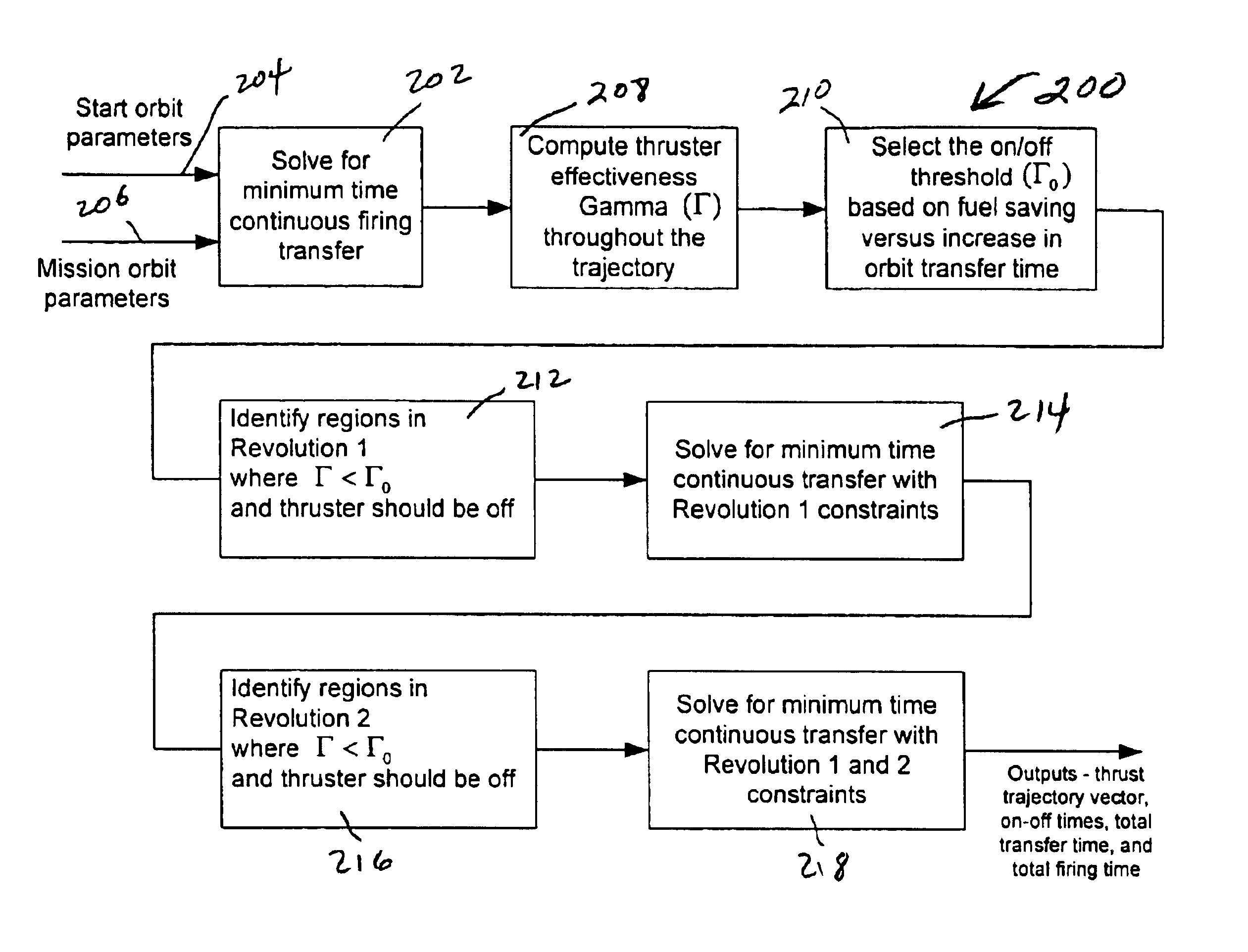
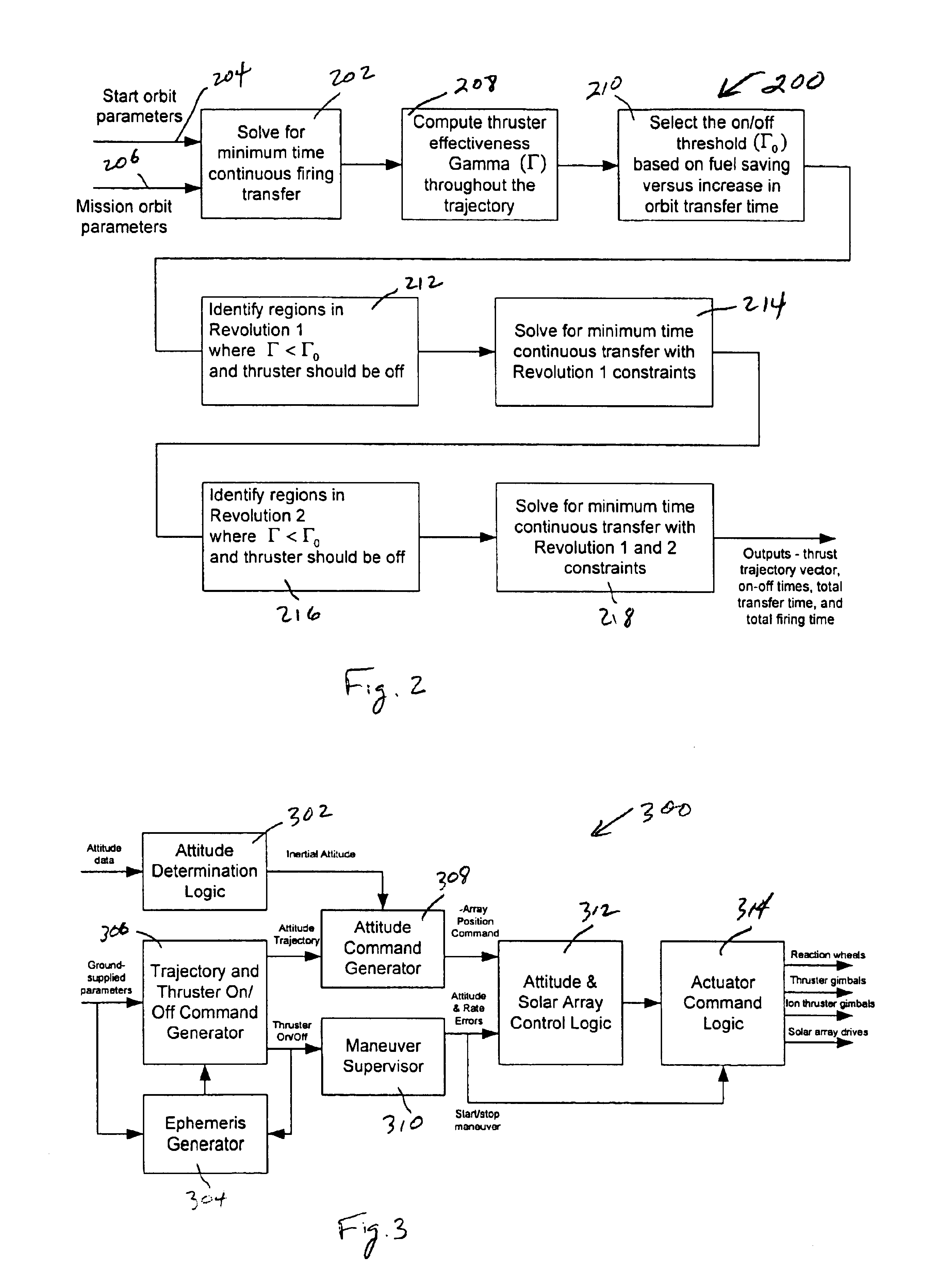
Prior-art systems use a continuous-firing orbit transfer strategy, in which the ion thrusters are fired almost continuously over some period to provide a transfer from an initial to a final orbit. One drawback of firing ion thrusters continuously to carry-out an orbit transfer is that there may be some portions of the orbit where firing the thrusters is of only marginal benefit. Thus during those portions of the orbit, fuel is expended, but only a very small useful change in the orbit is achieved. To address this problem, the systems and methods of the present invention determine a spacecraft thrust vector trajectory and off-firing regions that eliminate these inefficient thrusting regions. As a result, the spacecraft orbit transfer requires less fuel, and thus, larger, more capable payloads can be put in...


PUM


Abstract

The present invention relates generally to systems and methods for transferring a spacecraft from a first orbit to a second orbit. In accordance with one embodiment of the invention, the method comprises calculating thruster-off regions within an orbit transfer in which it is efficient to turn-off spacecraft thrusters, and in those thruster-off regions, turning off the spacecraft thrusters.

Description

BACKGROUND OF THE INVENTIONThe present invention relates to orbit transfer techniques, and more particularly to systems and methods for efficiently transferring a spacecraft from one orbit to another orbit.Typically, a spacecraft is launched into an initial orbit that differs from the final orbit that the spacecraft is to follow during its lifetime. A spacecraft launch vehicle places the spacecraft in its initial or launch vehicle insertion orbit. The launch vehicle, however, generally does not have sufficient capability to place the spacecraft into its mission orbit. As a result, the spacecraft must be transferred from its initial insertion orbit to its final mission orbit, typically by using a spacecraft on-board propulsion system.For a geosynchronous orbit (GEO) spacecraft, a velocity change (Delta-V) of approximately 1600 m / sec is needed to transfer the spacecraft from a typical injection orbit to a final GEO orbit. As one skilled in the art will appreciate, the time allocated t...

Claims


Application Information

Patent Timeline
IPC IPC(8): B64G1/00B64G1/40B64G1/22
CPCB64G1/007B64G1/405B64G1/2427B64G1/413
Inventor GOODZEIT, NEIL EVANRATAN, SANTOSH
Owner LOCKHEED MARTIN CORP
Learn More