Mine stopping and braces therefor

a technology of stopping and braces, which is applied in the direction of shaft equipment, shaft lining, surface mining, etc., can solve the problems of stopping bending or deflecting, high pressure differential, etc., and achieve the effect of convenient installation and maintenan

Inactive Publication Date: 2005-01-25
JACK KENNEDY METAL PRODS & BUILDINGS
View PDF35 Cites 24 Cited by
  • Summary
  • Abstract
  • Description
  • Claims
  • Application Information

AI Technical Summary

Benefits of technology

Among the several objects of this invention may be noted the provision of an improved mine stopping and stopping braces capable of use in large or high pressure mine passageways; the provision of such stopping and braces that will be effective in at least partially stopping the flow of air through the mine passageway; the provision of such stopping and braces that are easy to install and maintain without excessive attention.

Problems solved by technology

Further, the pressure differential across a stopping can be very high.
The high pressure differential and / or the large size of the mine passages that a stopping closes can subject the stopping to large forces which cause the stopping to bend or deflect.

Method used


Image

  • Mine stopping and braces therefor
  • Mine stopping and braces therefor
  • Mine stopping and braces therefor

Examples


Embodiment Construction

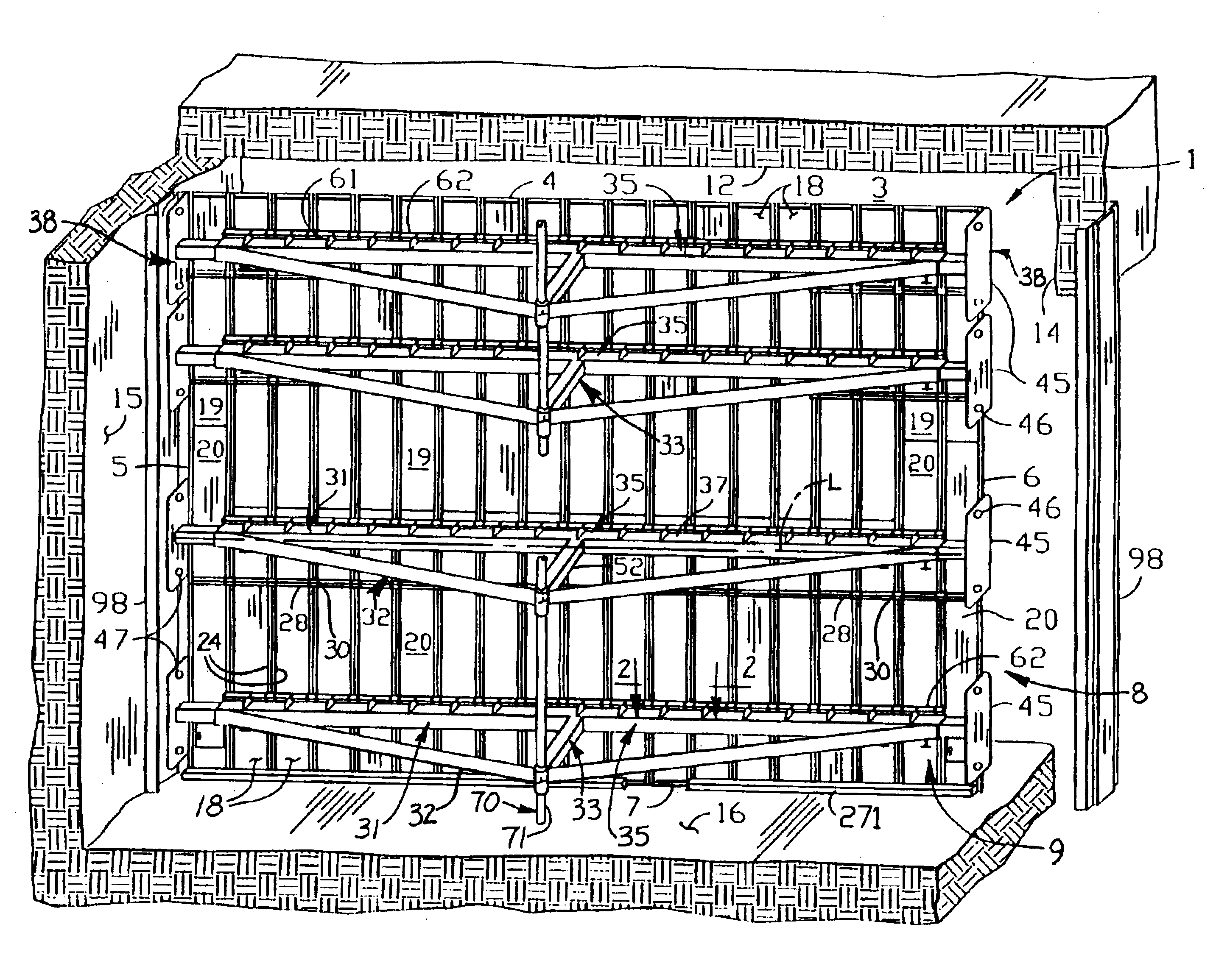
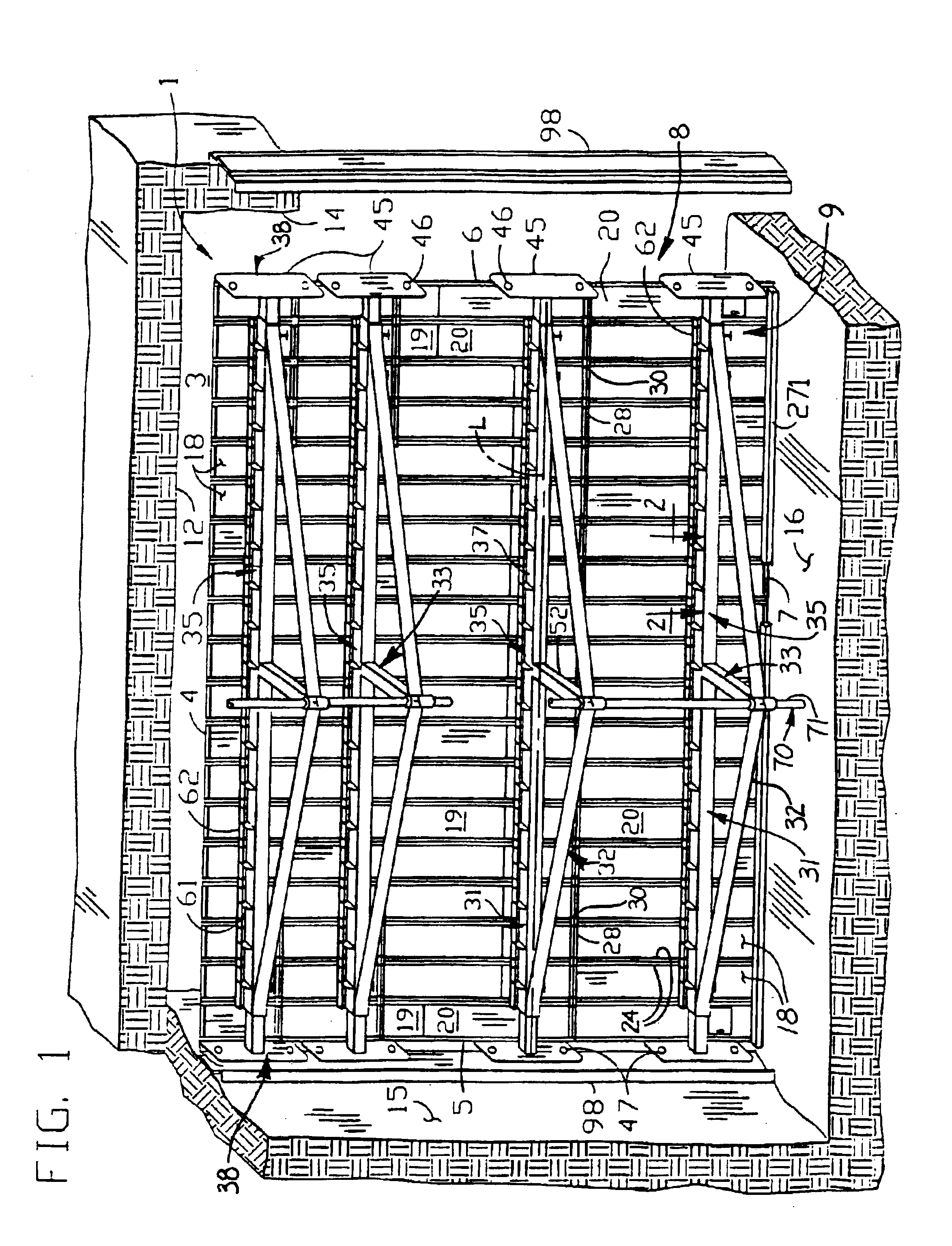
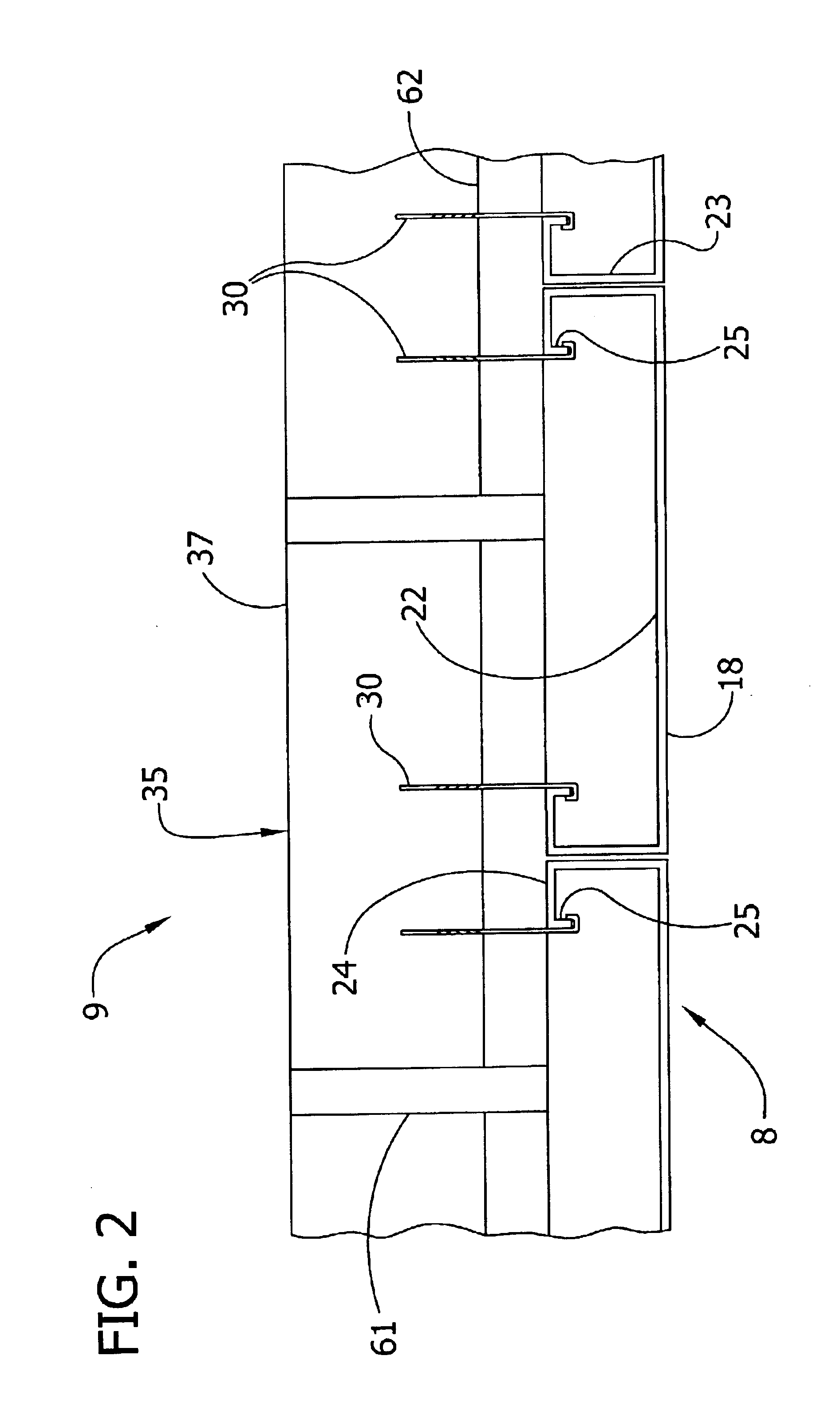
Referring to FIG. 1, the numeral 1 generally designates a high pressure stopping system of an embodiment of this invention adapted for use in mines to at least partially close a mine passageway 3. The system can be used to substantially or partially seal the passageway against air flow therethrough. In this embodiment, the stopping system 1 is used to substantially seal against air flow creating a pressure differential across the stopping system 1 with a normally high pressure side 8 and a normally low pressure side 9. This pressure differential applies force to the stopping system 1 in the direction of the higher pressure side 8 toward the lower pressure side 9. It is to be understood that the high pressure side 8 and the low pressure side 9 may switch under certain circumstances, but they are normally in one orientation. Also, the stopping may be incorrectly installed such that the high and low pressure sides 8, 9 are reversed. Sealing can be accomplished by having the top edge 4,...


PUM


Abstract

A mine stopping installed in a mine passageway includes a plurality of elongate panels extending generally vertically in side-by-side relation from a floor to a roof of the passageway to at least partially close the passageway. A generally horizontal elongate brace extends generally between the walls of the passageway adjacent to the panels. A generally vertical column extends from the floor to the roof and is adapted for reinforcing the brace. Braces and anchor beams for stoppings are also disclosed.

Description

BACKGROUND OF THE INVENTIONThis invention relates to mine stoppings and to braces for such mine stoppings.Mine stoppings are widely used in mine passageways to stop off the flow of air therethrough. A conventional metal stopping shown in U.S. Pat. No. 4,483,642 comprises a plurality of elongate extensible panels 7 extending vertically from the floor to the roof of the mine passageway and positioned in side-by-side relation across the passageway. (See FIG. 1 of the patent.)Some mine passages can be quite large, e.g., 20 feet wide and 10 feet high and even as large as 60 feet wide and 35 feet high. Further, the pressure differential across a stopping can be very high. The high pressure differential and / or the large size of the mine passages that a stopping closes can subject the stopping to large forces which cause the stopping to bend or deflect. Satisfactory high pressure stoppings are disclosed in our co-pending U.S. patent application Ser. No. 10 / 061,146 filed Feb. 1, 2002, and in...

Claims


Application Information

Patent Timeline
Patent Type & Authority Patents(United States)
IPC IPC(8): E21F1/00E21F1/10
CPCE21F1/10
Inventor KENNEDY, WILLIAM R.KENNEDY, JOHN M.
Owner JACK KENNEDY METAL PRODS & BUILDINGS
Why Eureka
Try Eureka