Cover joining structure for outboard engine unit

a technology for engine units and joining structures, applied in outboard propulsion units, marine propulsion, vessel construction, etc., can solve the problems of large sink mark problems, large skill and experience, and large impact on the overall appearance so as to reduce the overall weight of the outboard engine unit, eliminate sink mark problems, and improve the effect of appearan

Inactive Publication Date: 2005-01-25
HONDA MOTOR CO LTD
View PDF3 Cites 15 Cited by
  • Summary
  • Abstract
  • Description
  • Claims
  • Application Information

AI Technical Summary

Benefits of technology

Further, because the resin-made frame members are secured to the inner surfaces of the outer wall sections by welding or otherwise, the present invention can eliminate the sink mark problems of the conventional covering during molding of reinforcing ribs, and thus can readily form a covering of superior outer appearance for the outboard engine unit.
In an embodiment, each of the frame members is made of resin. Thus, the resin-made frame members can be readily secured reliably to the resin-made outer wall sections of the corresponding undercover members by vibration welding or other suitable means. Furthermore, because the frame members and outer wall sections are formed of resin, the present invention can achieve reduction in overall weight of the outboard engine unit while assuring enhanced rigidity.
In an embodiment, the cover joining structure further comprises a bolt inserted through the fixedly joining sections, provided on the frame members of the left and right cover members, in the front-and-rear direction, to thereby join together the left and right cover members. Because the left and right undercover members are joined together by the fastening bolt with no noticeable depressed and/or projecting surface formed on the abutted joining edge regions of the cover members, the joint between the cover outer wall sections can have a significantly improved outer appearance. This arrangement can avoid noticeable exposure of the bolt, fixedly joining sections, etc. on the joint between the outer wall sections of the cover members, thereby achieving a good appearance of the joint between the cover members.
In an embodiment, the cover joining structure further comprises a bolt inserted through the fixedly joining sections, provided on the frame members of the left and right cover members, in a vertical direction of the outboard engine unit, to thereby join together the left and right cover members. Because the left and right undercover members are joined together by the fastening bolt with no noticeable depressed and/or projecting surface formed on the abutted edge regions of the cover members, the joint between the cover outer wall sections can have a significantly improved outer appearance. This arr

Problems solved by technology

Due to such relatively great widths, concave and convex surfaces (projecting and depressed surfaces, i.e. surface unevenness) of the front and rear joining sections would considerably impair the overall outer appearance of the outboard engine unit.
Particularly, in the outboard engine unit, such concave and convex surfaces (surface unevenness) tend to be a great block when a large, smooth, continuous surface, such as a flush or even surface, is desired.
Acqui

Method used


Image

  • Cover joining structure for outboard engine unit
  • Cover joining structure for outboard engine unit
  • Cover joining structure for outboard engine unit

Examples


Embodiment Construction

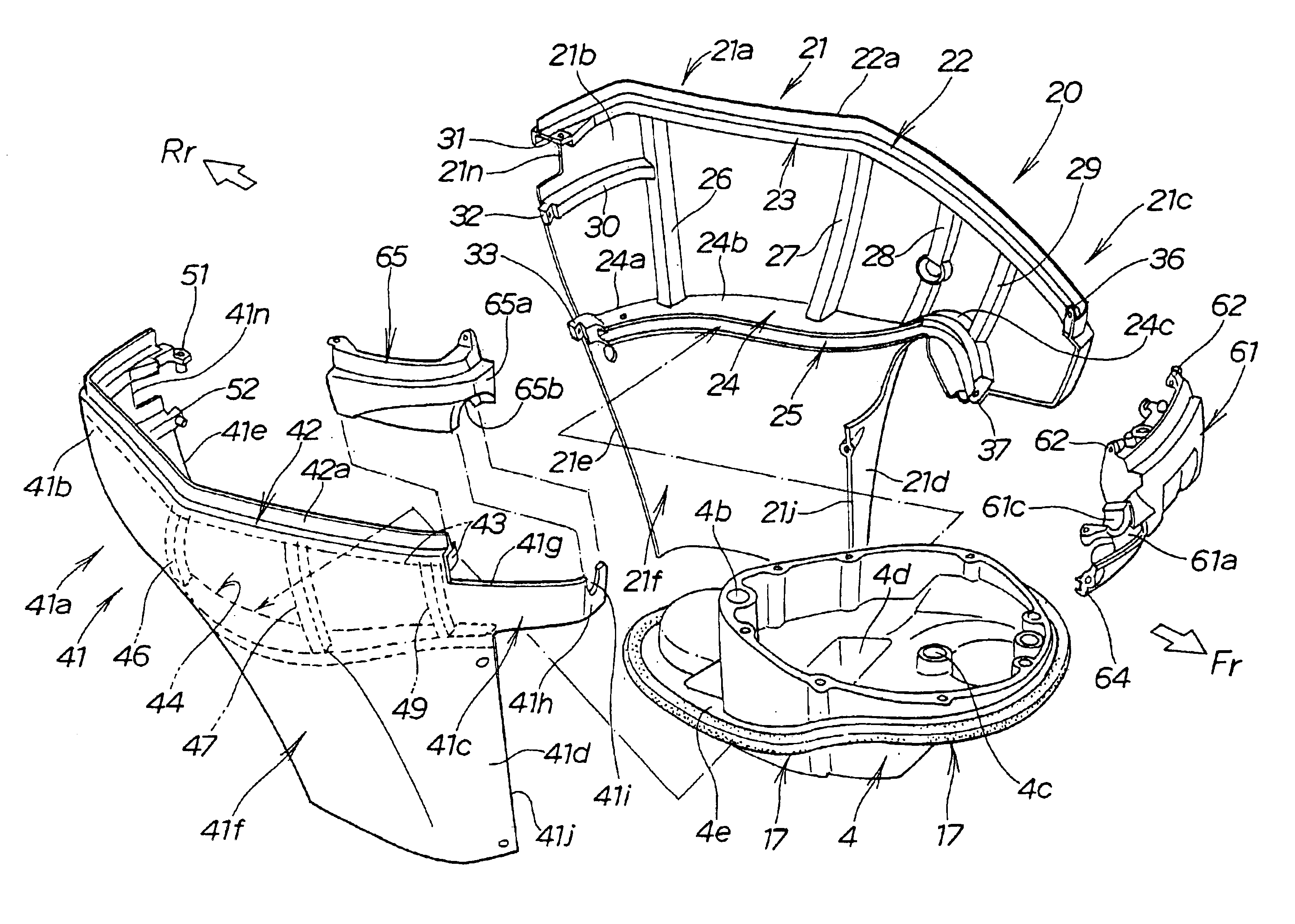
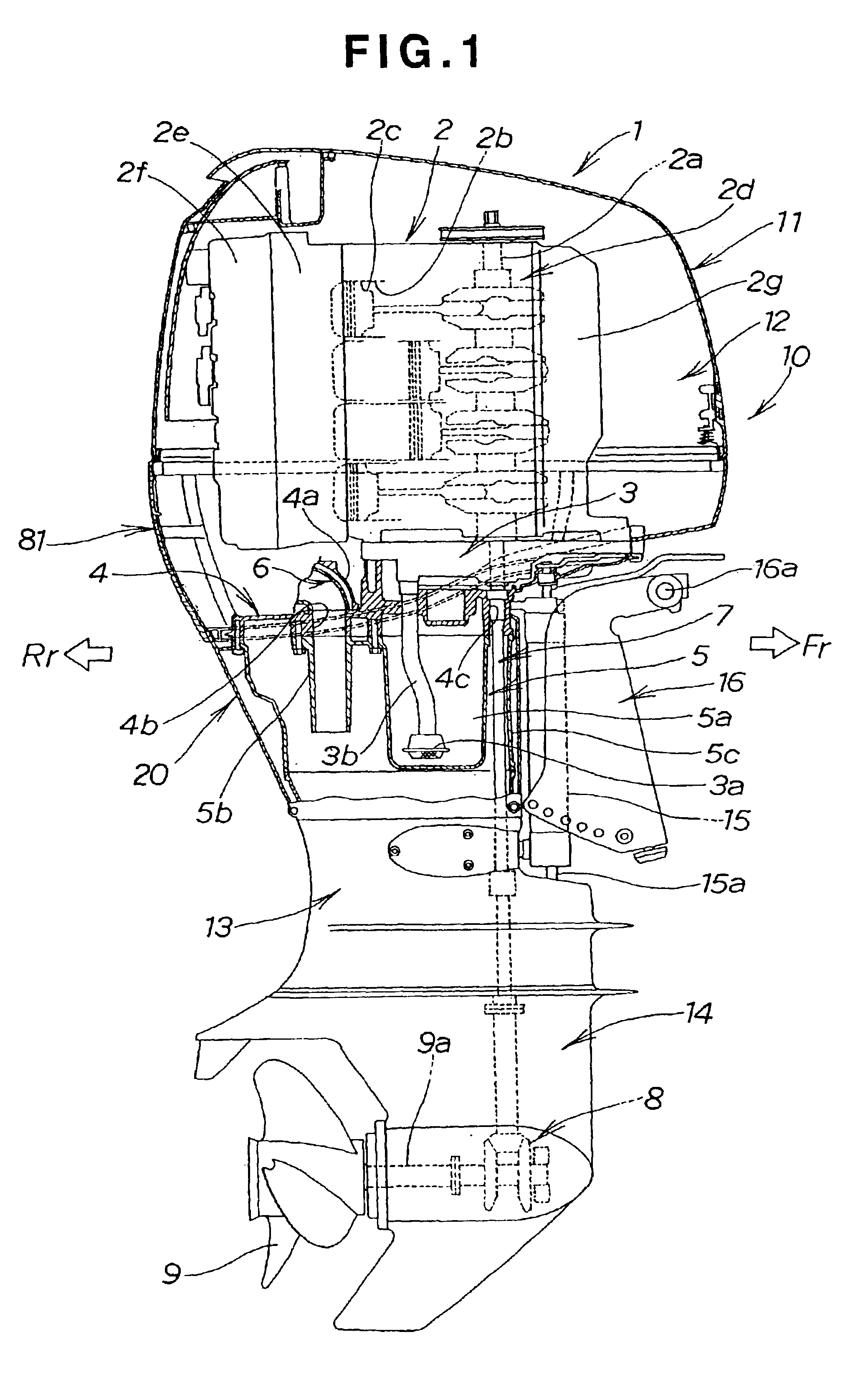
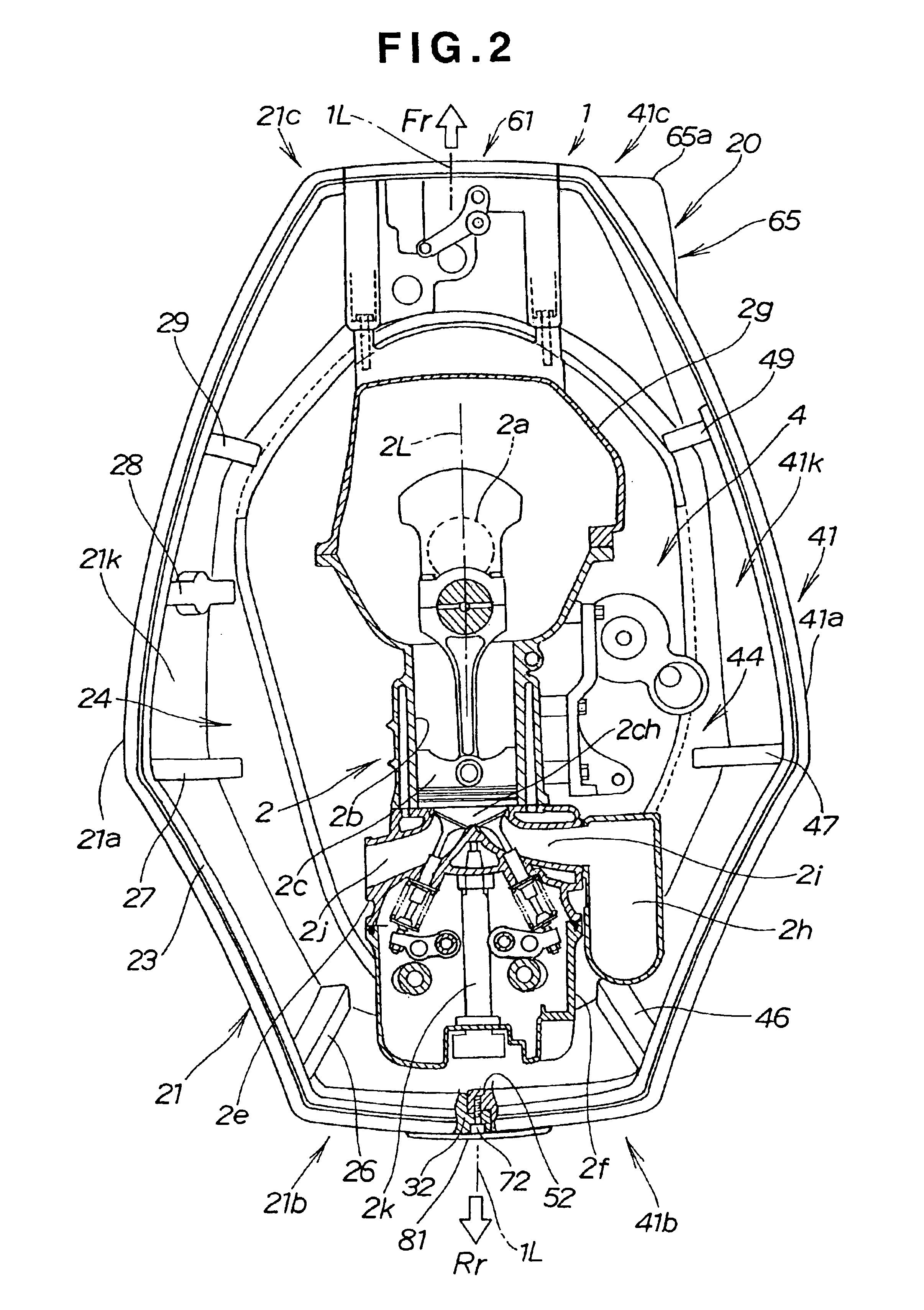
Reference is made initially to FIGS. 1 and 2. In these and other Figures, reference character “Fr” represents a forward propelled direction of the boat to which is applied the outboard engine unit of the present invention, while reference character “Rr” represents a rearward direction opposite from the forward propelled direction of the boat.

The outboard engine unit 1 of FIG. 1 comprises a casing assembly that supports thereon the engine 2, and a covering assembly that covers the engine 2 to form an engine space 12.

The engine 2 is a vertical-type engine having a crankshaft 2a elongated vertically. The engine 2 includes a plurality of cylinders 2b, which are provided in such vertical alignment that their respective horizontal center lines 2L (only one of which is shown in FIG. 2 ) all lie in a substantial middle portion between left and right inner side surfaces of the outboard engine unit and which extend generally in the front-and-rear direction of the outboard engine unit 1. Each ...


PUM


Abstract

Fixedly joining sections are provided on opposed joining edges of left and right undercover members defining part of an engine space of an outboard engine unit. The opposed joining edges are abutted against each other with the joining sections of the left and right undercover members overlapped in face-to-face relation with each other in a front-and-rear direction of the outboard engine unit. Fasteners, such as bolts, fasten together the overlapped joining sections in the front-and-rear direction, to thereby join together the left and right undercover members. The joining sections may be provided on frame members integrally secured to the respective inner side surfaces of resin-made outer wall sections of the left and right undercover members.

Description

FIELD OF THE INVENTIONThe present invention relates to an improved structure for joining together separate left and right cover members, such as those of an engine cover of an outboard engine unit.BACKGROUND OF THE INVENTIONVarious engine spaces of outboard engine units have been proposed, such as one that comprises a fixed lower casing and an upper covering detachably attached to the fixed lower casing, and one that comprises a lower casing, including a pair of left (port-side) and right (starboard-side) lower cover members, and an upper covering.One example of the engine spaces is known from Japanese Patent Laid-Open Publication No. SHO-62-18394. In the disclosed engine space, a lower engine cover, which covers a lower section of the engine, is composed of left and right lower cowls that are joined together with their respective edges abutted against each other along a substantially middle portion of the cover, to thereby constitute a lower half section of the engine space.FIG. 28...

Claims


Application Information

Patent Timeline
IPC IPC(8): B63H20/00B63H20/32F02B61/04F02B61/00
CPCF02B61/045B63H20/32
Inventor YASUDA, TOYOSHIYAZAKI, MAKOTOIDE, SHINICHI
Owner HONDA MOTOR CO LTD
Why Eureka
Try Eureka