Liquid handling system with automatically interchangeable cannula array

a liquid handling system and cannula technology, applied in the field of automatic liquid handling systems, can solve the problems of difficult correction complicated problems in testing, and difficult to solve in a large array system, so as to maximize the capacity of wellplate servicing, simple and rapid

Inactive Publication Date: 2005-01-25
ZYMARK CORP
View PDF5 Cites 35 Cited by
  • Summary
  • Abstract
  • Description
  • Claims
  • Application Information

AI Technical Summary

Benefits of technology

It is another object of the invention to provide a method of changing over a cannula array of a dispensing system that is simple and rapid, and may be conducted without significant interruption of the reliable oper...

Problems solved by technology

Such testing is especially cumbersome in research involving proteins in which numerous samples are mixed in a biologically compatible solution, such as Dimethyl Sulfoxide (DMSO).
However, although the efficiency in the number of samples increases by increasing the array size, problems in dealing with clogging and misdispensing also become more complicated as the array size and density increase.
Clogging of one or more of the cannulas, though may be detectable by computer software of the dispenser controller monitoring the syringe bodies, still can be difficult to correct in a large array system.
Removal of and replacement of a cannula array can introduce fluid pathway sealing problems or misalignment of the array that can cause the cannulas to “crash” into a wellplate when it is lowered if the cannulas miss their intended wells.
Additionally, in systems that use disposable plastic ...

Method used


Image

  • Liquid handling system with automatically interchangeable cannula array
  • Liquid handling system with automatically interchangeable cannula array
  • Liquid handling system with automatically interchangeable cannula array

Examples


Embodiment Construction

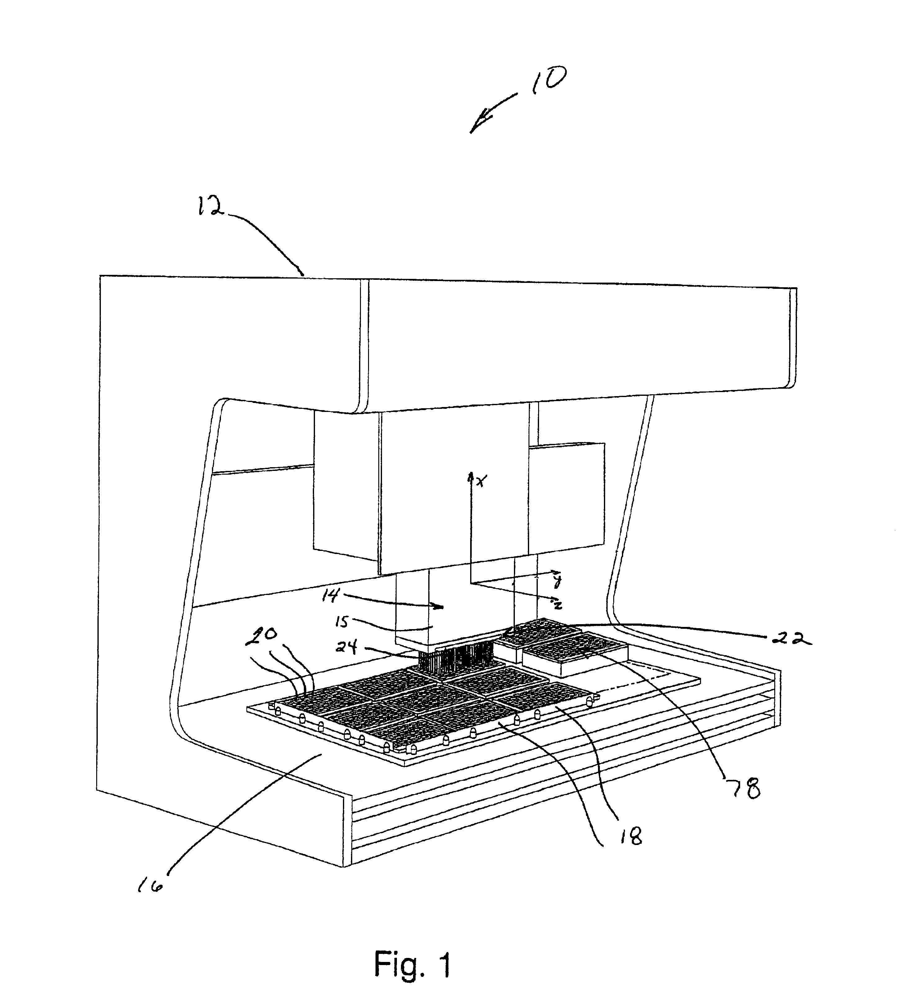
FIG. 1 shows a perspective view of an automated liquid handling system according to the present invention. The liquid handling system 10 comprises a cabinet 12, dispensing head assembly 14 and sample support surface 16. The support surface 16 holds a plurality of well plates 18. The dispensing head assembly comprises several components configured to carry out aspiration of liquid from or dispensing of liquid into the wells 20 of an individual wellplate. Preferably, the dispensing head assembly 14 is configured to move in one, two or three dimensions to reach wellplates arranged on support surface 16. Alternatively or in addition to the dispensing head movement, the support surface 16 may be configured to move in one, two or three dimensions to provide relative movement between the components and increase flexibility of the dispensing operation. Whether the dispensing head, the support surface or both components are configured to move is not important as long as relative movement bet...


PUM


Abstract

The present invention provides a liquid handling system capable of automated dispensing and reformatting operations by virtue of a quick-release cannula array mounting system that permits cannula arrays to be changed automatically by the system or manually by a user. Automated changing of the cannula array is carried out by relative movement of the dispensing head and the sample support surface to deliver the attached cannula array to a storage location, releasing the array from the dispensing head, and attaching a new cannula array. Relative movement between the dispensing head and sample support surface in at least two dimensions increases flexibility of the system and makes self-loading of the cannula array practical. The system provides advantages in time and accuracy of cannula array changeover procedures. The automated cannula array changeover capability permits automated wellplate reformatting procedures, which can be performed quickly and accurately.

Description

FIELD OF THE INVENTIONThe present invention pertains to the field of automated liquid handling systems.BACKGROUND OF THE INVENTIONAutomated liquid handling systems are designed to aspirate or dispense minute, accurate quantities of liquid for the purpose of transferring liquid from one reservoir to another. The systems are configured to aspirate liquid from and dispense liquid to standardized liquid reservoirs known as wellplates, which are configured to hold biological or chemical samples, usually suspended in a neutral liquid medium. Liquid handling systems comprise a dispensing head having one or more fluid pathways through which is controlled the dispensing of the liquid and a support surface for holding the wellplates in proximity to the dispensing head. The dispensing head and / or the support surface are configured to move relative to each other in at least one or more dimensions to facilitate dispensing and transfer of wellplates through the dispensing area.The fluid pathways ...

Claims


Application Information

Patent Timeline
IPC IPC(8): B01L3/02G01N35/10
CPCB01L3/0279G01N35/10B01L3/022G01N35/1074Y10T436/2575G01N2035/1039Y10T436/119163Y10T436/114998G01N2035/103
Inventor FRISWELL, DAVID R.DUNLAP, RAYMONDGRUBNER, GEORGEBERNAL, ENRIQUE
Owner ZYMARK CORP
Why Eureka
Try Eureka