Magnetron for microwave ovens

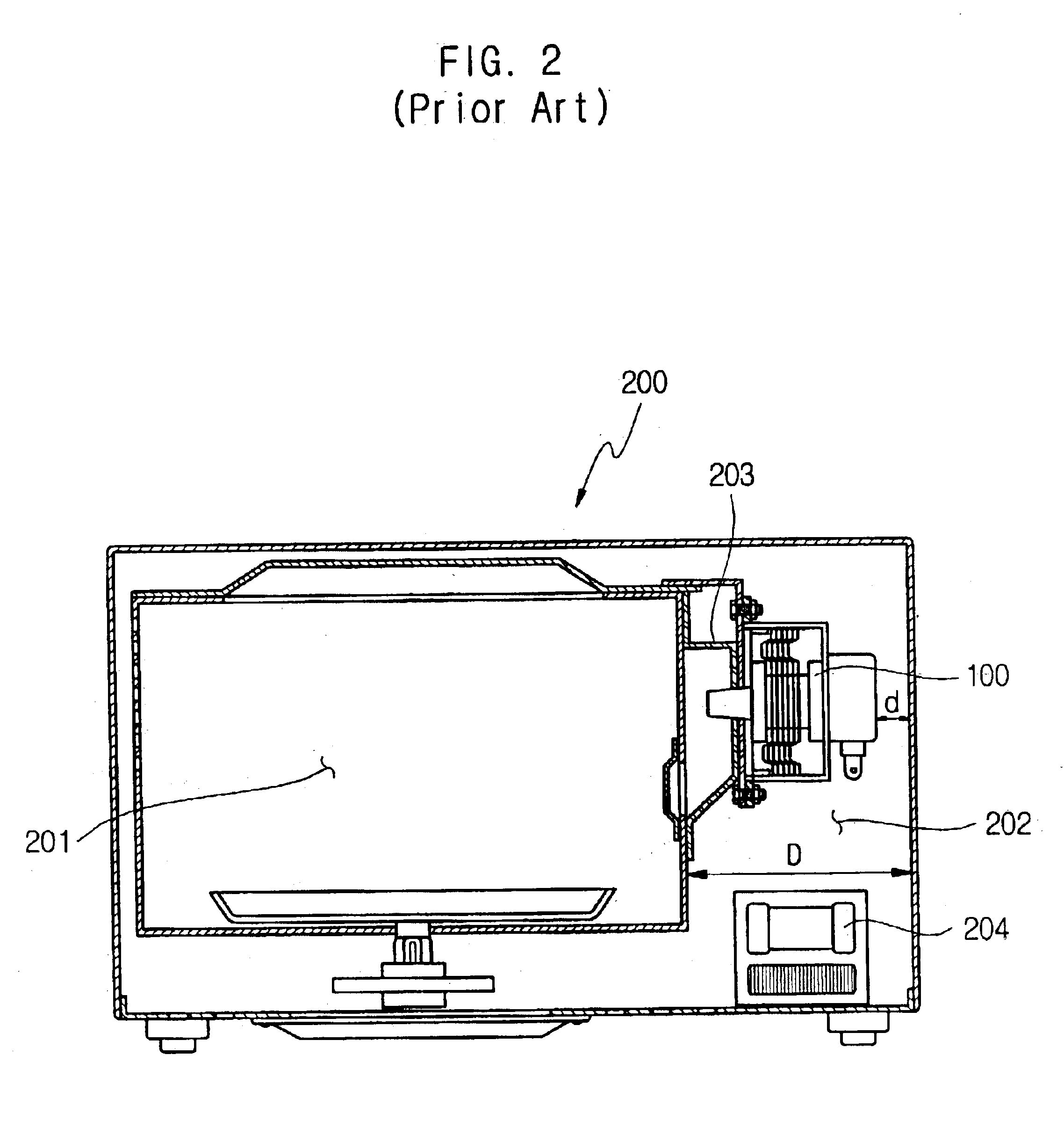
a microwave oven and magnetoelectric technology, applied in microwave heating, electric/magnetic/electromagnetic heating, transit tube leading-in arrangements, etc., can solve the problems of significant restriction in the design of the microwave oven b>200/b>, and the problem is fatal to small-sized microwave ovens having a cooking cavity

Inactive Publication Date: 2005-01-25
SAMSUNG ELECTRONICS CO LTD
View PDF8 Cites 8 Cited by
  • Summary
  • Abstract
  • Description
  • Claims
  • Application Information

AI Technical Summary

Benefits of technology

Accordingly, it is an aspect of the present invention to provide a microwave oven in which a height of a filter box is re

Problems solved by technology

For this reason, the conventional microwave oven is problematic in that a design of the microwave oven 200 is significantl

Method used


Image

  • Magnetron for microwave ovens
  • Magnetron for microwave ovens
  • Magnetron for microwave ovens

Examples


Embodiment Construction

Reference will now be made in detail to the present preferred embodiments of the present invention, examples of which are illustrated in the accompanying drawings, wherein like reference numerals refer to like elements throughout. The embodiments are described below in order to explain the present invention by referring to the figures.

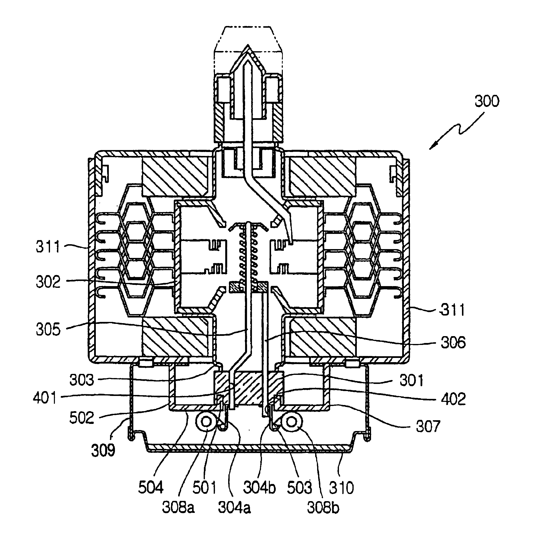
FIG. 3 is a longitudinal sectional view of a magnetron in accordance with an embodiment of the present invention. FIG. 4 is a perspective view showing the first and second insulators of FIG. 3. FIG. 5 is an enlarged sectional view of area A of FIG. 3.

As shown in FIG. 3, in a magnetron 300, a first insulator 301 of ceramic material having a height of 8 mm is welded to a bottom of a grounded lower shield cup 303 not only to seal an interior of a positive polar cylinder 302 in a vacuum state but also to prevent a dielectric breakdown phenomenon caused by a potential difference of about 4 KV between first and second terminals 304a and 304b or between first...


PUM


Abstract

A magnetron for microwave ovens including a second insulator interposed between a connection part and a bottom of a yoke to form a relatively lengthened insulation distance, or a molded insulating plate attached to a bottom of the filter box to reduce a distance between the connection part and a bottom of the filter box. In the magnetron, an entire height of the magnetron is reduced, so that a miniaturization of the magnetron can be implemented and a design of a product including the magnetron, such as a microwave oven, can be freely carried out, thus allowing an appearance of the product to be variously designed.

Description

CROSS-REFERENCE TO RELATED APPLICATIONThis application claims the benefit of Korean Application No. 2002-58413, filed Sep. 26, 2002, in the Korean Intellectual Property Office, the disclosure of which is incorporated herein by reference.BACKGROUND OF THE INVENTION1. Field of the InventionThe present invention relates generally to a magnetron for microwave ovens, and more particularly, to a magnetron for microwave ovens, which is provided with a filter box having a reduced height.2. Description of the Related ArtIn general, magnetrons are widely used to generate microwaves in home appliances, such as in microwave ovens, as well as in industrial applications, such as in high-frequency heating apparatuses, in particle accelerators and in radars.The general construction of such a magnetron is described with reference to FIG. 1.As shown in FIG. 1, in a magnetron 100, a plurality of vanes 102 that comprise a positive polar section together with a positive polar cylinder 101 are radially a...

Claims


Application Information

Patent Timeline
IPC IPC(8): H01J23/14H01J23/15H01J25/587H01J25/00H01J25/50H01J23/00H05B6/64
CPCH01J25/587H01J23/15
Inventor HAN, YONG-WOONJANG, SEONG-DEOGKANG, HAN-SEONGYEO, JOO-YONGHAN, DAE-SUNG
Owner SAMSUNG ELECTRONICS CO LTD
Why Eureka
Try Eureka