
Shape memory thermal exposure monitor

a monitor and memory technology, applied in the field of thermal exposure monitors, can solve the problems of device not using scales, device processing end existing haccp programs at the processing end of the chain are not equipped with proper tools, etc., to achieve convenient and effective regulatory tools, reduce liability, and reduce the risk of contamination of products

Inactive Publication Date: 2005-02-01
AKERS JEFFREY W +1
View PDF8 Cites 42 Cited by
  • Summary
  • Abstract
  • Description
  • Claims
  • Application Information

AI Technical Summary

Benefits of technology

Another object of this invention is to provide a cumulative thermal exposure monitor that can be used with perishable food products that will accurately indicate the degree of spoilage or deterioration.
Another object of this invention is to provide a cumulative thermal exposure monitor that can serve as an inexpensive, convenient and effective regulatory tool for HACCP programs and allow real time decisions to be made as to the safety or quality of a perishable product.
Another object of this invention is to provide a cumulative thermal exposure monitor that may reduce liability by indicating, package by package, whether the thermal history of a particular perishable product was within proper limits while it was in transit or storage.
A further object of this invention is to provide a cumulative thermal exposure monitor that is food-safe and has little danger of contaminating the product it is monitoring.
A still further object of this invention is to provide a cumulative thermal exposure monitor that is inexpensive to manufacture, may be disposable, and is economical to install on individual containers.

Problems solved by technology

Existing HACCP programs in place at the processing end of the chain are not equipped with proper tools to monitor all of the critical control points (CCP's) in the cold chain, and temperature related problems can still occur throughout the distribution chain.
This device does not utilize a scale because there is no degree of spoilage of blood (it is either considered good or bad).
Thus, prior art devices that merely indicate that a temperature threshold was achieved or exceeded at some point in time do not indicate the cumulative amount of heat energy absorbed within a preferred storage temperature range and whether, at any time, the cumulative heat energy absorbed has taken place for a period of time sufficient to cause any degree of deterioration based on the time and temperature thermal deterioration profile of the perishable product.

Method used


Image

  • Shape memory thermal exposure monitor
  • Shape memory thermal exposure monitor
  • Shape memory thermal exposure monitor

Examples


Embodiment Construction

The present invention utilizes the unique phase transition properties (shape memory and superelasticity) of shape memory materials such as “Shape Memory Alloys” (SMA) and “Shape Memory Polymers” (SMP). Shape memory alloys undergo a reversible phase transition in their crystal structure when heated from a low temperature form to a high temperature form. Upon heating or cooling, shape memory alloys do not completely undergo their phase transition at one particular temperature. Instead, the transition begins at one temperature (known as the start temperature) and is completed at another temperature (known as the finish temperature). Further, there is a difference in the transition temperatures upon heating from the first phase to the second phase (martensite to austenite for example in Ni—Ti) and cooling from the second phase to the first (austenite to martensite), resulting in a delay or “lag” in the transition. This difference is known as the transition temperature hysteresis. The tr...


PUM

PropertyMeasurementUnit
threshold temperaturesaaaaaaaaaa
temperaturesaaaaaaaaaa

Abstract

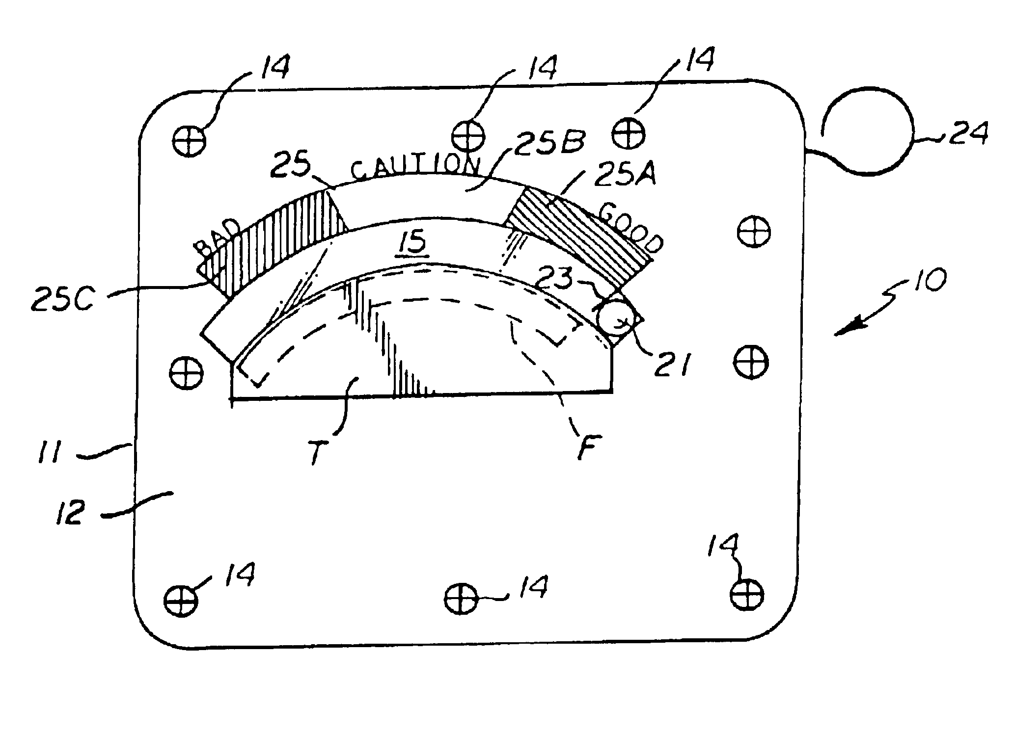
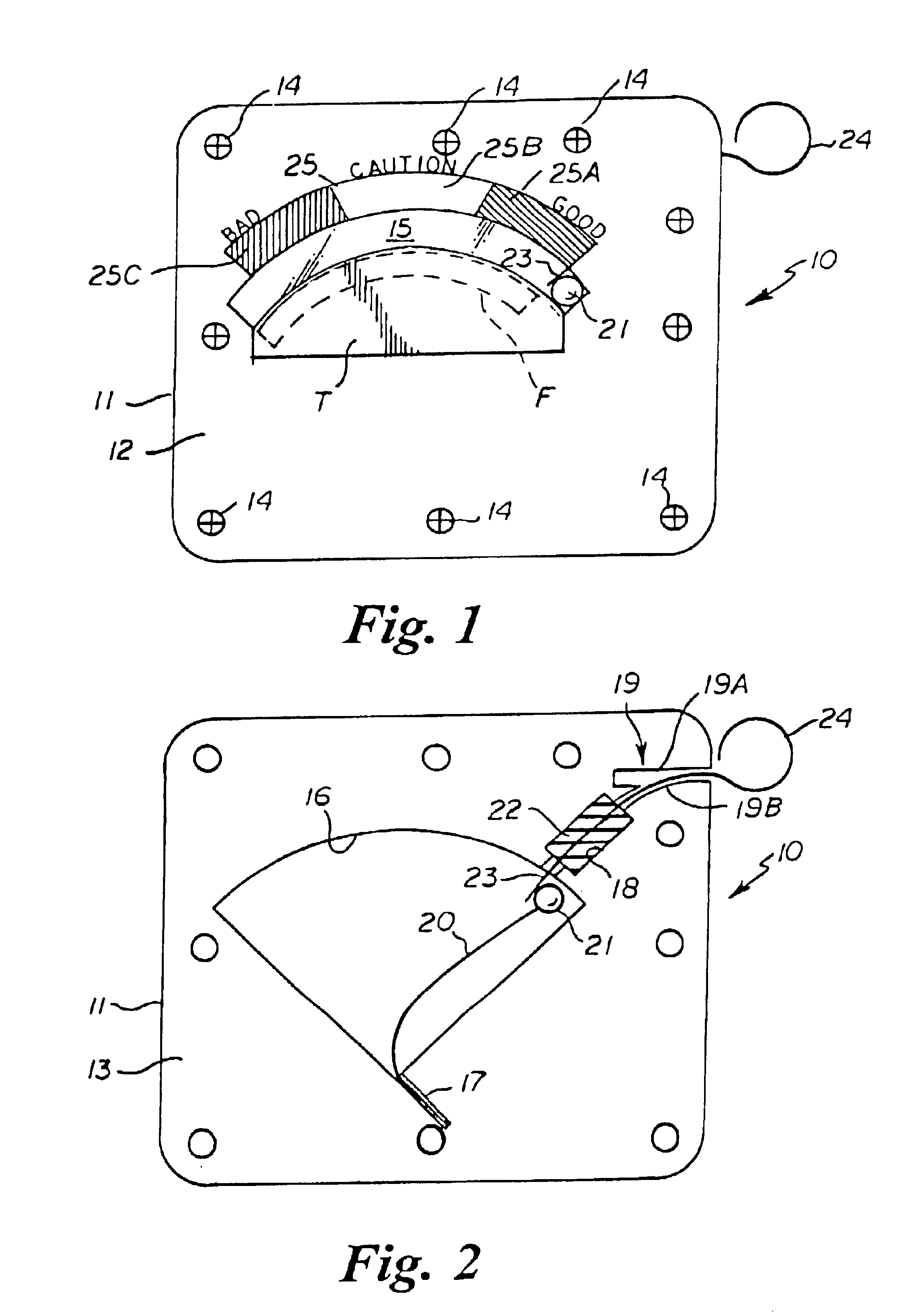
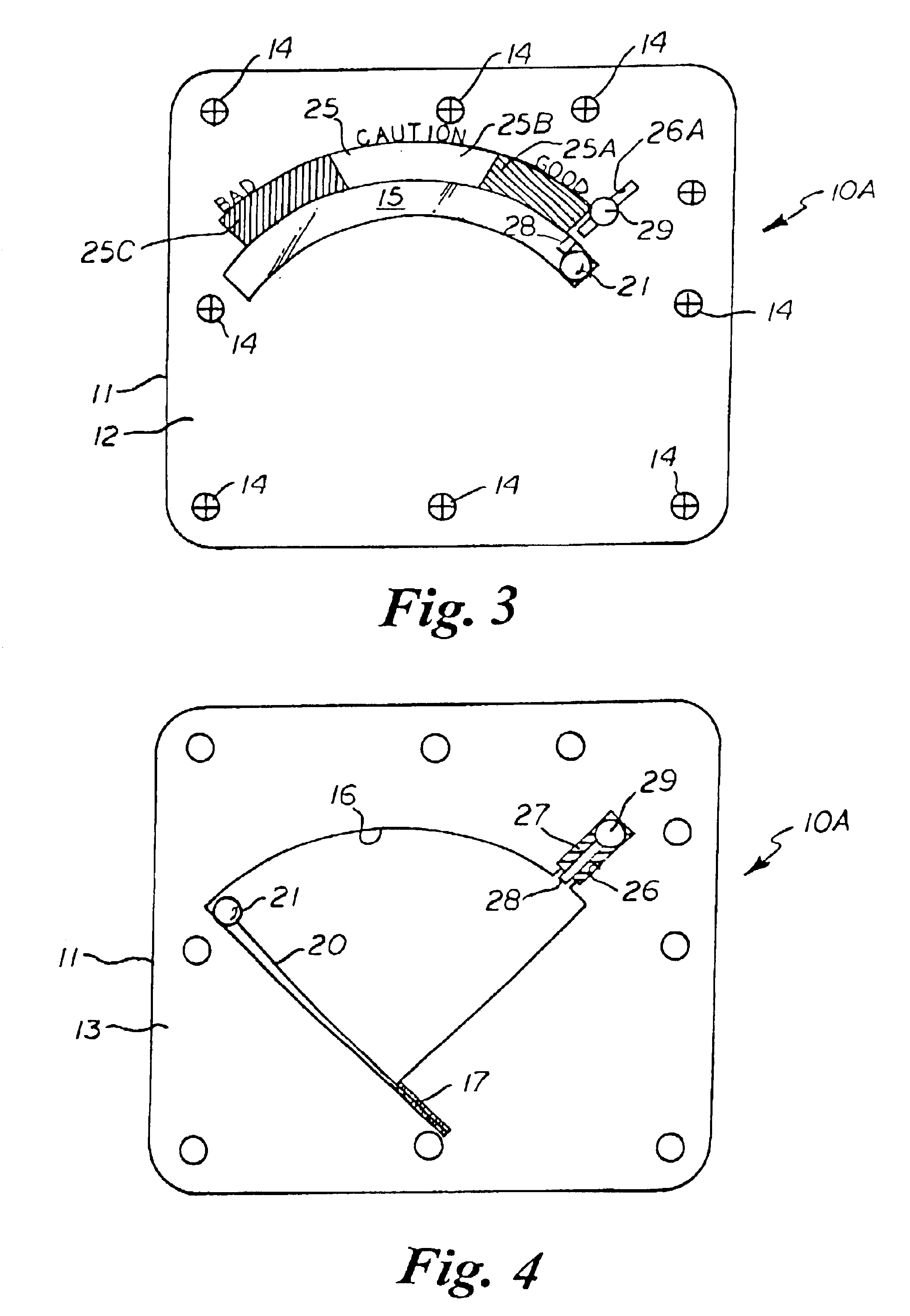
A cumulative thermal exposure monitor (10) having a housing (11) with a fluid sealed interior cavity (16) and a thermally-responsive member (20) therein formed of a shape memory material which moves an indicator (21), wherein the thermal properties of the housing, cavity, and shape memory material transition temperature range are calibrated relative to one another to function in mutual cooperation such that the thermally-responsive member gradually changes from a first shape to a second shape upon absorption of heat energy over time to closely match a thermal deterioration profile of a perishable product, and to indicate the cumulative amount of heat energy absorbed and whether, at any time, the temperature has been above a preferred storage temperature range for a period of time sufficient to cause any degree of deterioration based on a known time and temperature thermal deterioration profile of the perishable product.

Description

BACKGROUND OF THE INVENTION1. Field of the InventionThis invention relates generally to thermal exposure monitors, and more particularly to a cumulative thermal exposure monitor having a housing with a fluid sealed interior cavity and a thermally-responsive member therein formed of a shape memory material that moves an indicator wherein the thermal properties of the housing, cavity, and shape memory material transition temperature range are calibrated relative to one another to function in mutual cooperation such that the thermally-responsive member gradually changes from a first shape to a second shape upon absorption of heat energy over time to closely match a thermal deterioration profile of a perishable product, and to indicate the cumulative amount of heat energy absorbed and whether, at any time, the temperature has been above a preferred storage temperature range for a period of time sufficient to cause any degree of deterioration based on the known time and temperature therm...

Claims


Application Information

Patent Timeline
Patent Type & Authority Patents(United States)
IPC IPC(8): G01K5/00G01K3/00G01K3/04G01K5/48
CPCG01K5/483G01K3/04
Inventor AKERS, JEFFREY W.ZERKUS, JAMES MICHAEL
Owner AKERS JEFFREY W
Learn More