Exhaust gas purifying device for internal combustion engine

a technology of exhaust gas purification device and internal combustion engine, which is applied in the direction of exhaust treatment electric control, machines/engines, mechanical equipment, etc., can solve the problems of increasing the probability of ammonia slip, the reaction time of nox catalyst is long, and the response time of nox sensor is long

Active Publication Date: 2010-10-14
DENSO CORP
View PDF7 Cites 33 Cited by
  • Summary
  • Abstract
  • Description
  • Claims
  • Application Information

AI Technical Summary

Benefits of technology

[0041]It is considered for a response time to extend according to decreasing the temperature of the NOx catalyst because a reaction time of the NOx catalyst is changed according to changing the temperature of the NOx catalyst. Further, the more the reaction time in the NOx catalyst is long, the more the response time of the NOx sensor becomes long (that is, the more the responsibility of the NOx sensor decreases).
[0042]In this point of view, in the exhaust gas purifying device as another aspect of the present invention, the abnormality diagnosis means changes the diagnosis period of time based on a temperature of the NOx catalyst. This makes it possible to perform the abnormality diagnosis while considering the response time of the NOx sensor, and to suppress an occurrence of an incorrect diagnosis.

Problems solved by technology

However, it is difficult to specify whether a detection signal of the NOx sensor is generated by the presence of NOx or ammonia.
Even if there is a high probability of abnormal state when the NOx sensor placed at a downstream side outputs a detection signal of a large value, it is impossible to determine whether such a large detection signal from the NOx sensor is caused by the occurrence of ammonia slip or the presence of NOx contained in the exhaust gas.
Therefore the above type of a NOx sensor cannot specify the cause of generating such abnormal condition, namely, which is caused by the occurrence of ammonia slip or the presence of NOx.
That is, there is a probability of increasing the ammonia slip when the added amount of urea water is forcedly changed without determining whether the increasing of the output value of the NOx sensor placed at the downstream side of the unit having NOx catalyst is caused by ammonia slip or the presence of NOx contained in the exhaust gas.

Method used


Image

  • Exhaust gas purifying device for internal combustion engine
  • Exhaust gas purifying device for internal combustion engine
  • Exhaust gas purifying device for internal combustion engine

Examples


embodiment

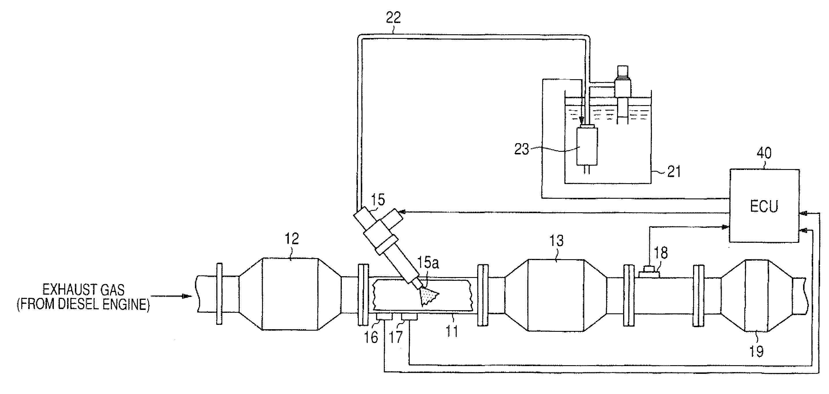
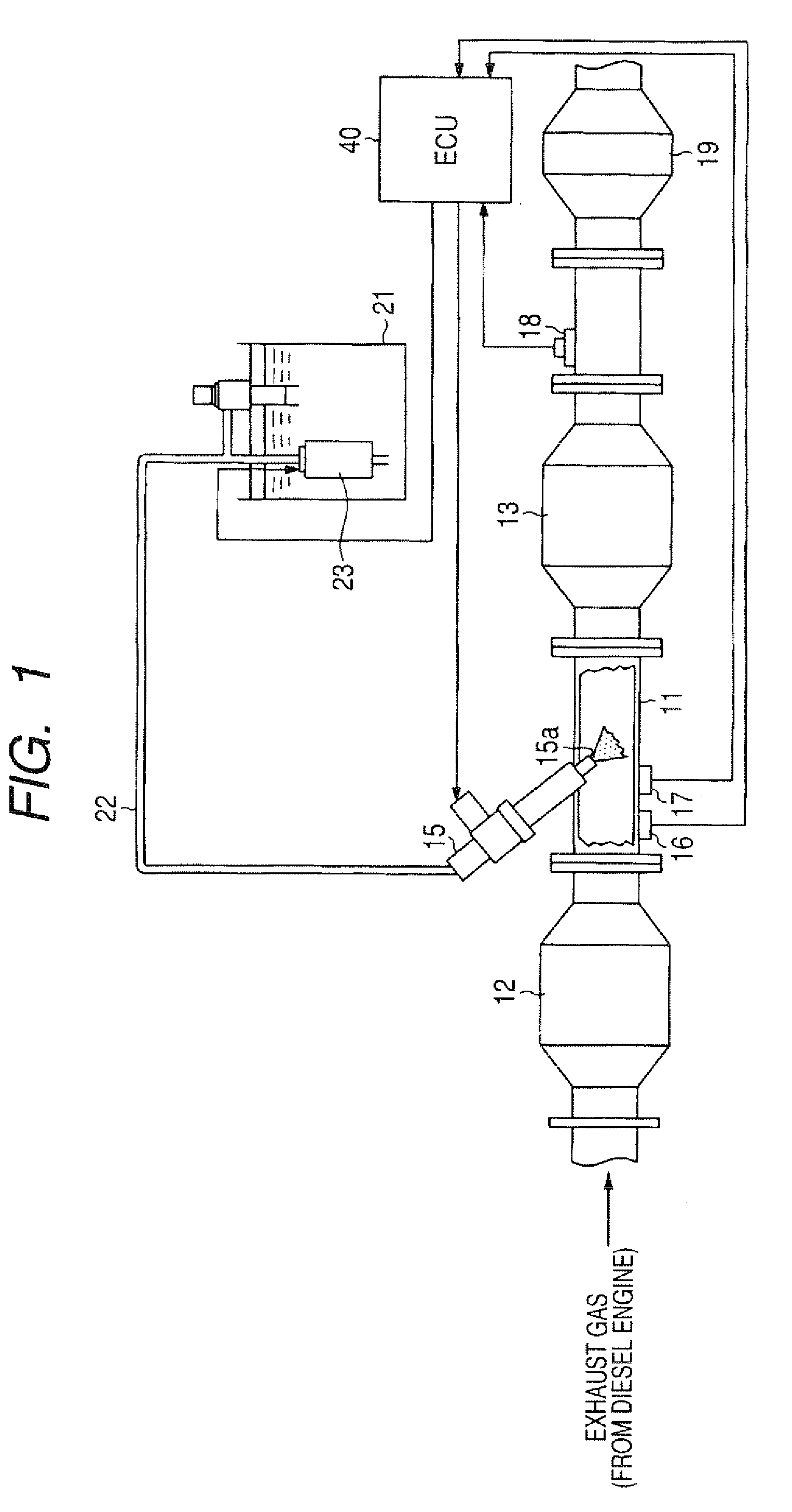
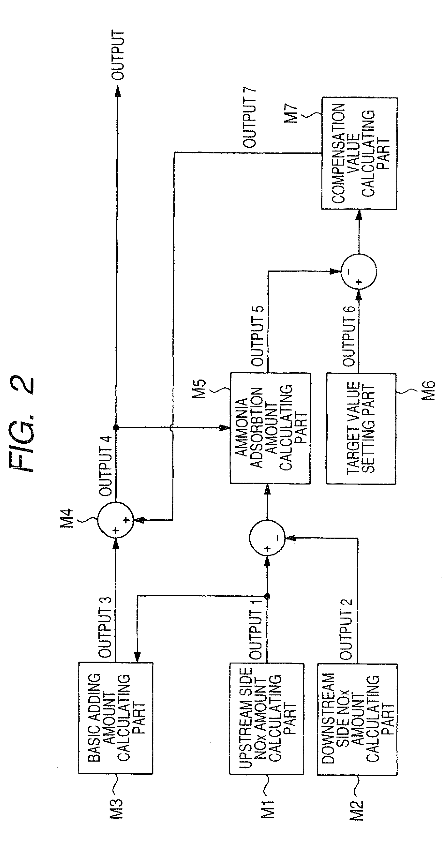
[0052]A description will be given of an exhaust gas purifying system, with reference to FIG. 1 to FIG. 6, to which the exhaust gas purifying device according to an embodiment of the present invention is applied. The exhaust gas purifying system shown in FIG. 1 is capable of purifying NOx contained in an exhaust gas emitted from an internal combustion engine such as a diesel engine (not shown). For example, there is a urea SCR (Selective Catalytic Reduction) system as the exhaust gas purifying system which is capable of purifying NOx contained in an exhaust gas by using a selective reduction catalyst. The structure of the urea SCR system as the exhaust gas purifying system will be explained in detail.

[0053]FIG. 1 is a view showing a schematic configuration of such a urea SCR system as the exhaust gas purifying system according to the embodiment of the present invention.

[0054]As shown in FIG. 1, the urea SCR system is comprised of various types of actuators and sensors, and electric c...


PUM


Abstract

An exhaust gas purifying system for a diesel engine has an ECU, a passage of exhaust gas, a unit having SCR catalyst, a NOx sensor placed at a downstream side of the unit, and a urea water adding valve placed at an upstream side of the unit. The SCR catalyst in the unit selectively adsorbs ammonia, and selectively purifies NOx contained in an exhaust gas emitted from the diesel engine by the adsorbed ammonia. The ECU changes the urea water adding amount, and performs abnormality diagnosis based on the detection result of the NOx sensor while changing an adding amount of the urea water. The ECU uses a first condition to indicate the presence of an excess NOx amount in the exhaust gas, and a second condition to indicate there is no error cause by the ammonia adsorption on the SCR catalyst.

Description

CROSS-REFERENCE TO RELATED APPLICATION[0001]This application is related to and claims priority from Japanese Patent Application No. 2009-97886 filed on Apr. 14, 2009, the contents of which are hereby incorporated by reference.BACKGROUND OF THE INVENTION[0002]1. Field of the Invention[0003]The present invention relates to an exhaust gas purifying device to be applied to an exhaust gas purifying system for internal combustion engines such as diesel engines. The exhaust gas purifying system is generally comprised of an exhaust gas pipe, a urea water adding valve, an unit having selective catalytic reduction (SCR) capable of selectively purifying nitrogen oxide (NOx) contained in an exhaust gas emitted from the internal combustion engine by using ammonia as a reductant (or a reducing agent), and one or more NOx sensors.[0004]2. Description of the Related Art[0005]There have been developed selective catalytic reduction (SCR) systems, and some of them have been put in practice. Such a SCR...

Claims


Application Information

Patent Timeline
Patent Type & Authority Applications(United States)
IPC IPC(8): F01N11/00F01N9/00F01N3/10
CPCF01N3/208F01N11/00F01N2560/026Y02T10/24F01N2610/02Y02T10/47F01N2570/10F01N2900/1622Y02T10/12Y02T10/40
Inventor SHIMOMURA, OSAMUSAKATA, MASAKAZUMARUYAMA, MASATOSHITOCHIKAWA, KAZUHARU
Owner DENSO CORP
Why Eureka
Try Eureka