Magnet coil arrangement

a technology of magnet coils and plug caps, which is applied in the direction of resistors, coupling device connections, and electromagnets, etc., can solve the problems of increasing the contact resistance between the contact lug and the screw head, unable to provide adequate electrical contact, and inability to exclude the possibility of the plastic of the plug cap changing its characteristics over the course of tim

Inactive Publication Date: 2005-02-01
BOSCH REXROTH AG
View PDF3 Cites 11 Cited by
  • Summary
  • Abstract
  • Description
  • Claims
  • Application Information

AI Technical Summary

Problems solved by technology

Even if the screw is tightened during assembly with a torque which is sufficient to make electrical contact, it is impossible to preclude the possibility of the plastic of the plug cap changing its characteristics over the cour

Method used


Image

  • Magnet coil arrangement
  • Magnet coil arrangement
  • Magnet coil arrangement

Examples


Embodiment Construction

Identical components are provided with the same reference symbols.

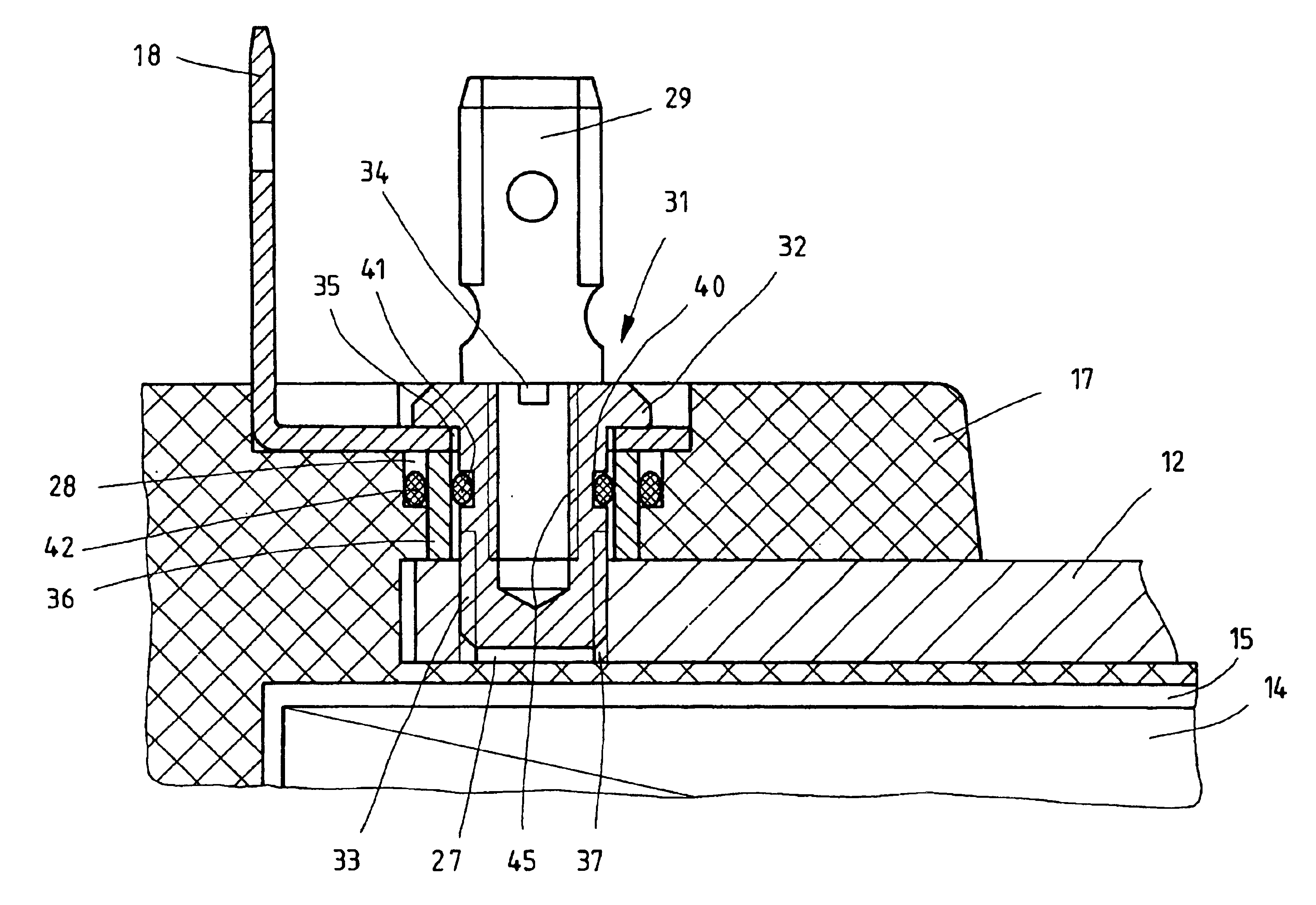
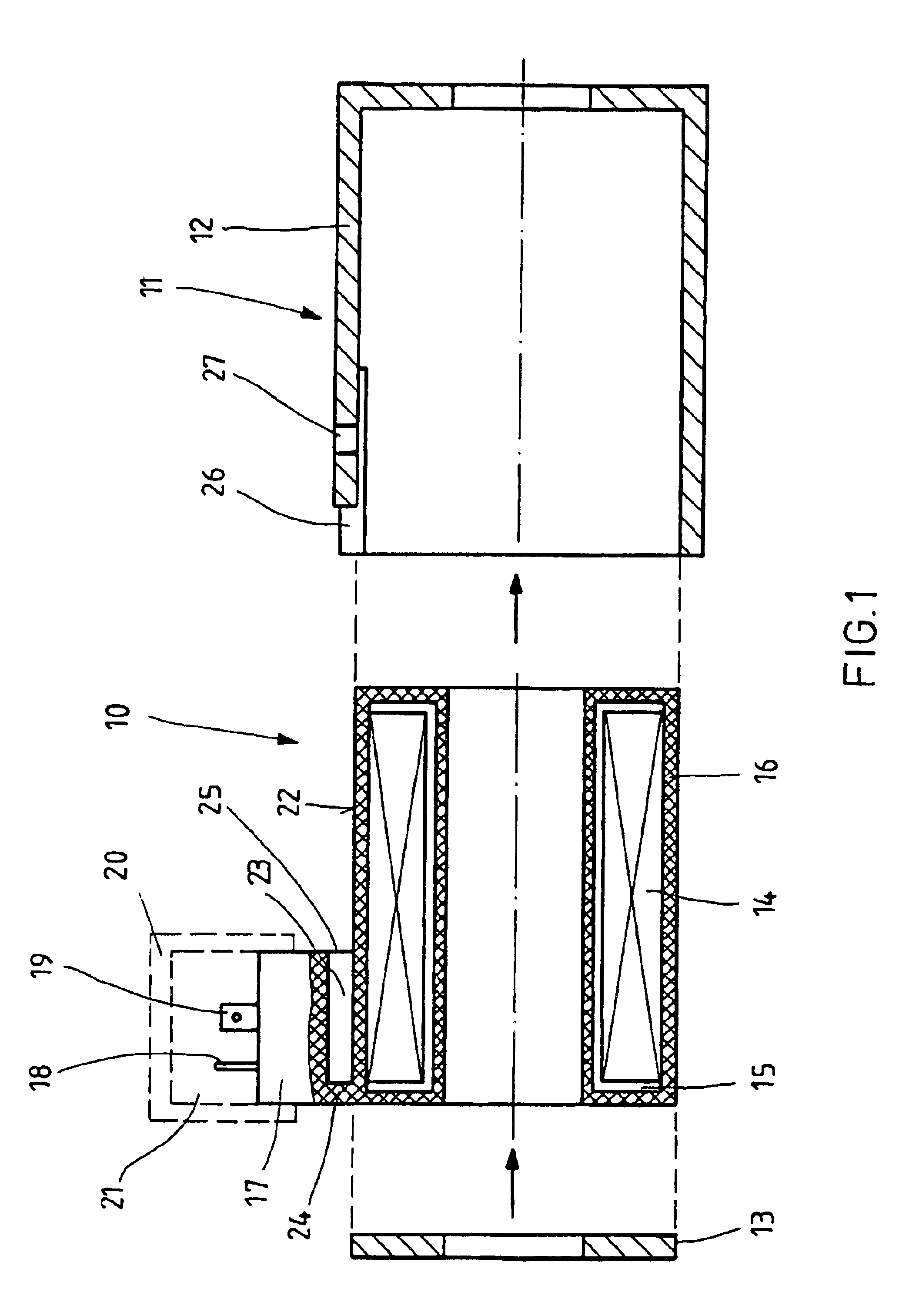
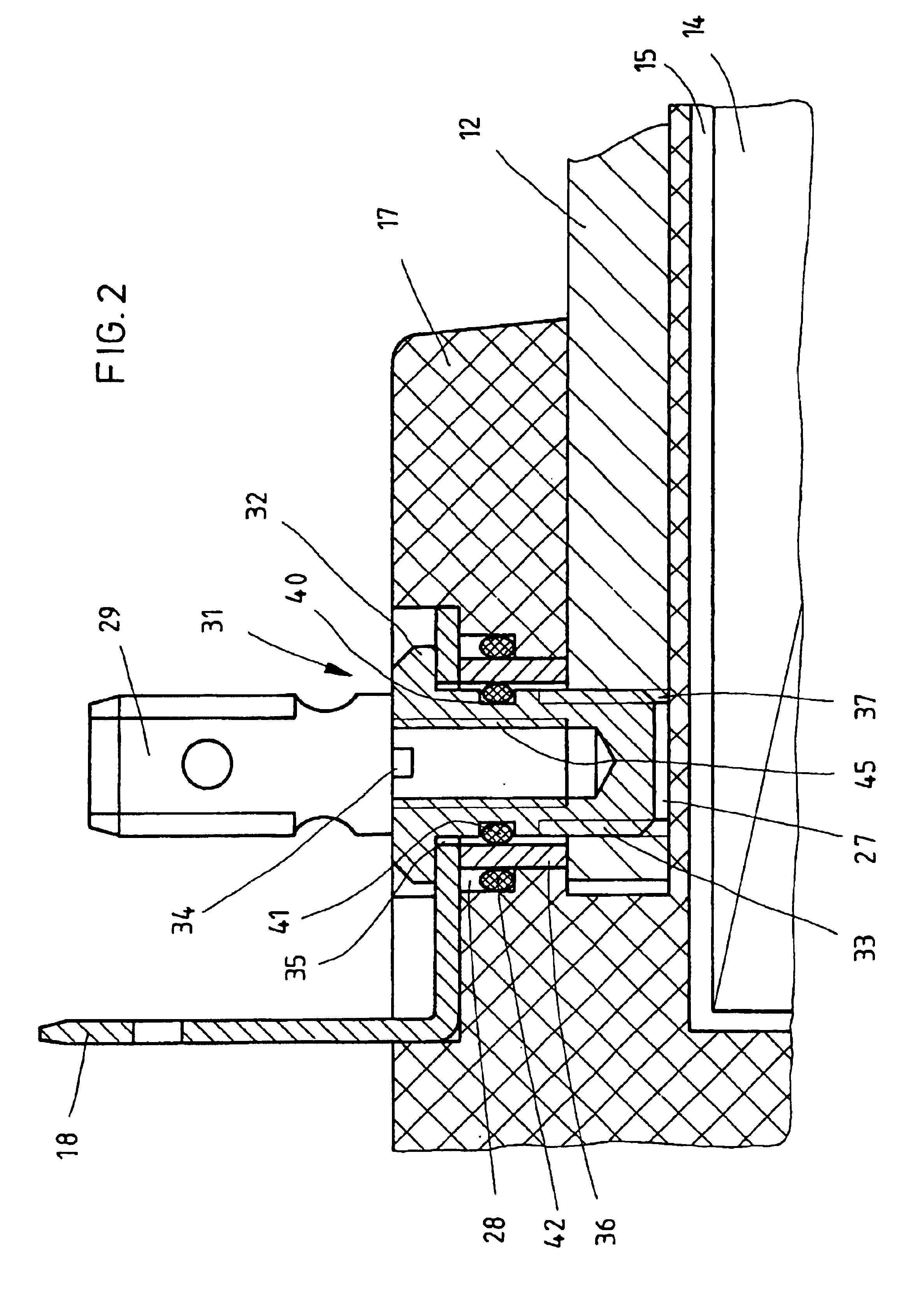
FIG. 1 shows the mechanical configuration of a magnet coil arrangement according to the invention, in the form of an exploded drawing. The magnet coil arrangement comprises an encapsulated coil 10 and a metal housing 11, which is formed from a coil pot 12 and a pole plate 13. The encapsulated coil 10 comprises a coil former 15, which is provided with a winding 14, is extrusion-coated with plastic 16, and on which a plug cap 17 which is provided with three contact lugs is integrally formed. The cross section of the contact lugs is rectangular. Only the contact lugs 18 and 19, of the three contact lugs, can be seen in FIG. 1. The contact lug 18 is associated with the protective ground conductor connection. The contact lug 19 is connected to one of the two winding ends of the coil 14. The contact lug which is connected to the other winding end of the coil 14 is concealed by the contact lug 19. The electrical conductors a...


PUM


Abstract

According to the invention, the coil of a magnet coil arrangement has a coil body which comprises a winding (14) and is extruded with plastic (17). A plug-in base with contact connectors is formed on the coil, wherein one of the connectors is used for connection of the grounding conductor (18). A metallic housing is placed over the coil. Connection of said metallic housing to the contact connector associated to the grounding conductor is achieved by means of a connection element which is guided through a recess of the plug-in base. A sealing element (42) disposed between the connection element and the recess prevents penetration of a fluid from a region between the metallic housing and the coil, into the region where a connector is connected to the contact connectors. In order to improve the electrical connection between the contact connector associated to the grounding conductor and the metallic housing, for a connection element (31) which is threaded in the metallic housing, a cylindrical metallic part is placed between the contact connector and the metallic housing. A respective sealing element (41, 42) is placed between the connection element and the metallic cylindrical part as well as between said part and the recess of the plug-in base. Such magnet coil arrangements are used in electromechanically-controlled hydraulic valves in which metallic parts accessible from outside must be connected to a grounding conductor.

Description

FIELD AND BACKGROUND OF THE INVENTIONThe invention relates to a magnet coil arrangement having an encapsulated coil, which comprises a coil former that is provided with a winding and is extrusion coated with plastic, and having a metal housing which is pushed over the encapsulated coil and surrounds it, as claimed in the precharacterizing clause of claim 1.A magnet coil arrangement of this type is known from DE 198 54 100 A1. A coil former which is provided with a winding is extrusion coated with plastic and forms an encapsulated coil. A plug cap is integrally formed on the encapsulated coil. Contact lugs are held in the plug cap, two of which are connected to the ends of the winding, while a third is associated with the protective ground conductor connection. The electrical connection is made via a connecting plug which is plugged onto the contact lugs. The housing of the connecting plug provides an external seal for the contact area which is formed by it and the plug cap. A metal ...

Claims


Application Information

Patent Timeline
IPC IPC(8): H01R4/28H01F7/06H01R4/64H01R4/34H01F27/04H01F27/02
CPCH01F7/06H01R4/64H01R4/34H01F27/022H01F2007/062H01F27/04
Inventor STITZ, MATTHIASWITTIG, KARL-HEINZKERN, HANS-JURGEN
Owner BOSCH REXROTH AG
Why Eureka
Try Eureka