Eureka AIR delivers breakthrough ideas for toughest innovation challenges, trusted by R&D personnel around the world.

Connector and method of operation

a technology of connecting rods and connecting rods, applied in the field of connecting rods, can solve the problems of prone to being dislodged from the cable end, and prone to being dropped or otherwise lost by the outer sleeve component, and achieve the effect of reducing the volume of the outer first cavity

Inactive Publication Date: 2005-02-01
PPC BROADBAND INC
View PDF121 Cites 250 Cited by
  • Summary
  • Abstract
  • Description
  • Claims
  • Application Information

AI Technical Summary

Benefits of technology

Also the present invention is directed to a coaxial cable connector comprising first body means for coupling to a coaxial cable, and including a post means for defining an inner first cavity, and further including a connector body means coupled to the post means and defining therebetween an outer first cavity, the post means having a first opening and a second opening each communicating with the inner first cavity, and the connector body means having at least one opening communicating with the outer first cavity, the first and second openings of the post means allowing for passage of at least a portion of the coaxial cable, and the outer first cavity allowing for entry of at least another portion of the coaxial cable; and fastener means for movably engaging the first body means and defining a second cavity having a first opening and a second opening each communicating with the second cavity, the fastener means being coupled onto the connector body means in a first configuration, and the first and second openings of the fastener means allowing for passage of a portion of the coaxial cable, and capable of being coupled onto the connector body means in a second configuration for decreasing the volume of the outer first cavity.
In addition, the present invention is directed to a method of positioning a connector on a coaxial cable, the coaxial cable comprising a center conductor, an insulator core, an outer conductor, and a sheath, comprises preparing an end of the coaxial cable by separating the center conductor and insulator core from the outer conductor and sheath; providing a first body member including a post member defining an inner first cavity, and further including a connector body coupled to the post member and defining an outer first cavity therebetween, the post member having a first opening and a second opening each communicating with the inner first cavity, and the connector body having at least one opening communicating with the outer first cavity; providing a second body member defining a second cavity having a first opening and a second opening each communicating with the second cavity; movably fastening the second body member onto at least a portion of an outer surface of the connector body in a first configuration; inserting the prepared coaxial cable end through the second opening of the second body member and extending the center conductor of the prepared coaxial cable end out of second opening of post member; and moving second body member on connector body to a second configuration so as to decrease the volume of outer first cavity such that the first body member engages the outer conductor and sheath of the coaxial cable.

Problems solved by technology

These radial compression type end connectors suffer from a common disadvantage in that prior to being mounted on the cable ends, the outer sleeve components are detached and separated from the inner post and / or connector members.
As such, the outer sleeve components are prone to being dropped or otherwise becoming misplaced or lost, particularly, as is often the case, when an installation is being made outdoors under less than ideal weather conditions.
Thus, mishandling or loss of the outer sleeve component remains a serious problem during the critical installation phase.
Before the clamped position is achieved, the end connector is only loosely assembled on and is thus prone to being dislodged from the cable end.
This again creates problems for the installer.

Method used


Image

  • Connector and method of operation
  • Connector and method of operation
  • Connector and method of operation

Examples


Embodiment Construction

In the description which follows, any reference to either direction or orientation is intended primarily and solely for purposes of illustration and is not intended in any way as a limitation to the scope of the present invention. Also, the particular embodiments described herein, although being preferred, are not to be considered as limiting of the present invention.

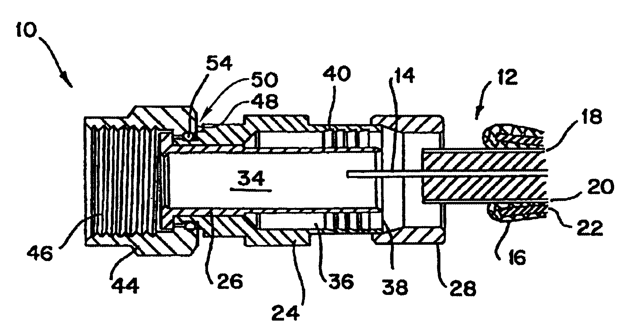
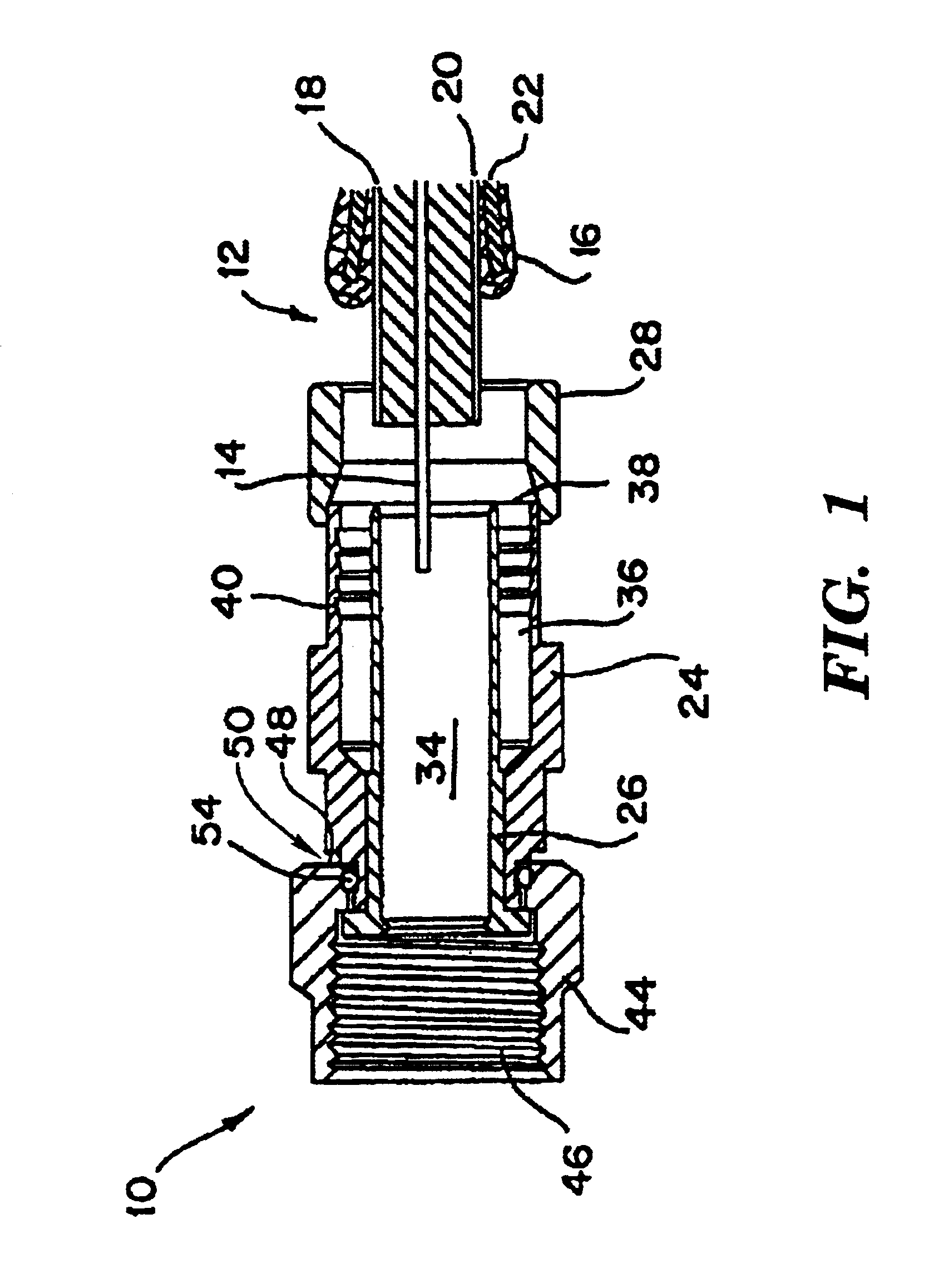
Referring to FIG. 1, a connector 10 in accordance with one preferred embodiment of the present invention is shown adjacent to the prepared end of a cable 12. In the example illustrated, cable 12 can be a known coaxial type having an electrical center conductor 14 surrounded by and spaced radially inwardly from a braid conductor 16 by a foil 18 and an insulator core 20. A dielectric covering or sheathing jacket 22 surrounds the braid 16 and comprises the outermost layer of the cable. Although an exemplary coaxial cable has been described, the connector 10 of the present invention can also be used with coaxial cables havi...


PUM


Abstract

A connector includes a connector body, a post member, and a fastener member. In one embodiment, the connector provides for coupling a coaxial cable having a center conductor, an insulator core, an outer conductor, and a sheath to a terminal device. A nut coupled to either the connector body or post member can be used on the connector to make the connection to the device. The post member has a cavity that accepts the center conductor and insulator core of a coaxial cable. An outer cavity is formed by the connector body and the post member such that the outer conductor and the sheath of a coaxial cable are positioned therebetween. The fastener member, in a pre-installed first configuration is movably fastened onto the connector body. The fastener member can be moved toward the nut into a second configuration in which the fastener member coacts with the connector body so that the connector sealingly grips the coaxial cable.

Description

FIELD OF THE INVENTIONThis invention relates to connectors used to couple cables to equipment ports, terminals, or the like. The invention is particularly useful in, although not limited to, universal connectors for coaxial cables of the type employed in the cable television industry.BACKGROUND OF THE INVENTIONIn using electronic devices such as televisions and video tape machines, it is desired to connect such devices either together or to other sources of electronic signals. Typically, a television may be hooked up to a cable service that enters the home through coaxial cables. Such cables are connected to the television by use of one or more connectors.The conventional coaxial cable typically contains a centrally located electrical conductor surrounded by and spaced inwardly from an outer cylindrical braid conductor. The center and braid conductors are separated by a foil and an insulator core, with the braid being encased within a protective sheathing jacket. In some typical coa...

Claims


Application Information

Patent Timeline
Patent Type & Authority Patents(United States)
IPC IPC(8): H01R9/05
CPCH01R9/0521
Inventor MONTENA, NOAH P
Owner PPC BROADBAND INC
Why Eureka
Eureka Blog
Learn More