High-voltage or medium-voltage switch device with combined vacuum and gas breaking

a high-voltage or medium-voltage switch and gas breaking technology, which is applied in the direction of air-breaking switch, high-tension/heavy-dress switch, electrical apparatus, etc., can solve the problems of not being able to withstand vacuum switch, not satisfying the above-type sequence, and relatively long arcing tim

Inactive Publication Date: 2005-02-01
ALSTOM TECH LTD
View PDF7 Cites 18 Cited by
  • Summary
  • Abstract
  • Description
  • Claims
  • Application Information

AI Technical Summary

Benefits of technology

Advantageously, for applications in which the device according to the invention is intended for use as a circuit-breaker in a high-voltage network, the displacement means are such that the respective contacts of the vacuum switch and the gas switch separate simultaneously or with a short time-delay.

Problems solved by technology

However, the above kind of sequence is not satisfactory if the hybrid high-voltage breaker device combines a gas switch for a standard high voltage greater than 72.5 kV with a vacuum switch for a standard medium voltage less than 52 kV.
This operation implies a relatively long arcing time, which a vacuum switch is not designed to withstand.
In particular, with the above kind of device it is not possible to obtain simultaneous or delayed separation of the contacts of the vacuum switch relative to separation of the contacts of the gas switch.
The above device has some disadvantages from a mechanical point of view, however.
This results in high transverse stresses on the vacuum switch, which can limit is mechanical durability.
However, the separation movement of the contacts of the vacuum switch is driven by the operating rod of the gas switch, with the result that the contacts of the vacuum switch must not separate until opening of the contacts of the gas switch is completed.
It is obviously not possible with the above device to achieve simultaneous or slightly delayed separation of the contacts of the vacuum switch relative to separation of the contacts of the gas switch.

Method used


Image

  • High-voltage or medium-voltage switch device with combined vacuum and gas breaking
  • High-voltage or medium-voltage switch device with combined vacuum and gas breaking
  • High-voltage or medium-voltage switch device with combined vacuum and gas breaking

Examples


Embodiment Construction

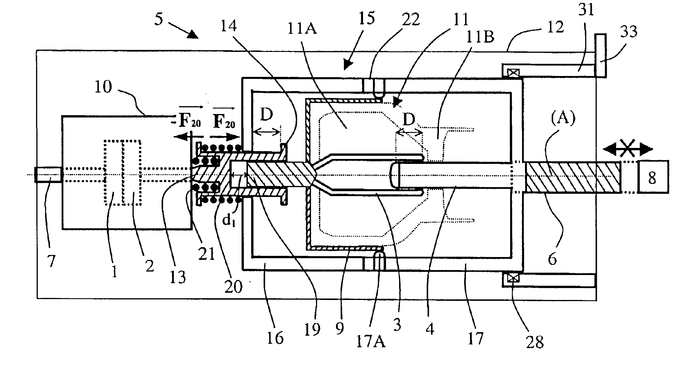
The hybrid breaker device 5 shown in FIG. 1 exhibits global symmetry of revolution about an axis A. It includes a vacuum switch 10 containing a first pair of arc contacts 1 and 2. A first contact 1 is fixed and is permanently connected to an end bushing 7 of the device 5. A second contact 2 is mobile in the axial direction A. The device also includes a gas switch 11 electrically connected in series with the vacuum switch. The gas switch comprises a second pair of arc contacts consisting of third and fourth contacts 3 and 4. The third contact 3 is fixed into the enclosure 12 by retaining means shown in FIGS. 8 and 9. The fourth contact 4 is mobile in the axial direction A and attached to an operating rod 6 connected to the operating mechanism 8 of the device 5. The two switches 10 and 11 are disposed in a common enclosure 12 filled with a dielectric gas.

In the embodiment shown, the mobile contact 4 is inserted into the fixed contact 3 to a particular overlap distance when the breaker...


PUM


Abstract

A hybrid high-voltage or medium-voltage breaker device includes an enclosure filled with a dielectric gas, a vacuum switch, a gas switch and an operating rod. The vacuum switch includes a fixed first arc contact and a second arc contact which can move in translation in an axial direction of the enclosure. The gas switch includes a fixed or quasi-fixed third arc contact and a fourth arc contact which can move in translation. The operating rod is connected to the fourth contact. The device also includes a connection arrangement for electrically connecting the second and third contacts and a displacement arrangement connected to the connection arrangement and to the rod which separates the second and fourth contacts from the first and third contacts, respectively.

Description

BACKGROUND OF THE INVENTION1. Field of the InventionThe invention relates to a hybrid high-voltage or medium-voltage switch device. The qualifier “hybrid” applies to the breaking action, which is of a mixed type in which two different breaking techniques cooperate. In particular, a switch device is qualified as a hybrid device if it includes a vacuum switch closing a first pair of arc contacts and further includes a gas switch comprising a second pair of arc contacts.2. Description of the Prior ArtA device of the above type is disclosed in U.S. Pat. No. 3,038,980. It comprises an enclosure filled with a dielectric gas and having a longitudinal axis; the two switches are disposed inside the enclosure and electrically connected in series; the operating mechanism of the device is disposed outside the enclosure. The mechanism for actuating the contacts of the two switches is relatively simple, in the sense that one of the two contacts of the gas switch is attached to an adjacent mobile ...

Claims


Application Information

Patent Timeline
Patent Type & Authority Patents(United States)
IPC IPC(8): H01H33/14H01H33/04H01H33/66H01H33/915H01H33/985
CPCH01H33/143H01H33/6661
Inventor TRESY, MICHELPERRET, MICHELDUFOURNET, DENIS
Owner ALSTOM TECH LTD
Why Eureka
Try Eureka