Axial adjustable tie-down stretch cord terminus

a technology of stretch cord and terminus, which is applied in the direction of snap fasteners, buckles, bicycle equipment, etc., can solve the problems of not being adjustable and the load applied by the cord therefor tends to rock the hook, and achieve the effect of improving the performance of us

Inactive Publication Date: 2005-02-08
HAMPTON PRODS INT
View PDF12 Cites 23 Cited by
  • Summary
  • Abstract
  • Description
  • Claims
  • Application Information

AI Technical Summary

Benefits of technology

Objects of the invention include a stretch cord terminus, the position of which can be adjusted along a stretch cord or bungee cord, the cord then being locked to the terminus at the selected position: which transfers the bungee cord load substantially axially to the hook of the terminus; which does not involve rotation of the hook as a result of loads imparted thereto; and which provides improved performance in use.

Problems solved by technology

One problem with this terminus is that axial loads imparted to the cleat, when the cord is locked therein, pull the hook in a manner which tends to cause it to rotate.
The load applied by the cord therefor tends to rock the hook.
Some hooks suitable for use with bungee cord provide the load axially to the hook, but these are not adjustable.

Method used


Image

  • Axial adjustable tie-down stretch cord terminus
  • Axial adjustable tie-down stretch cord terminus

Examples


Embodiment Construction

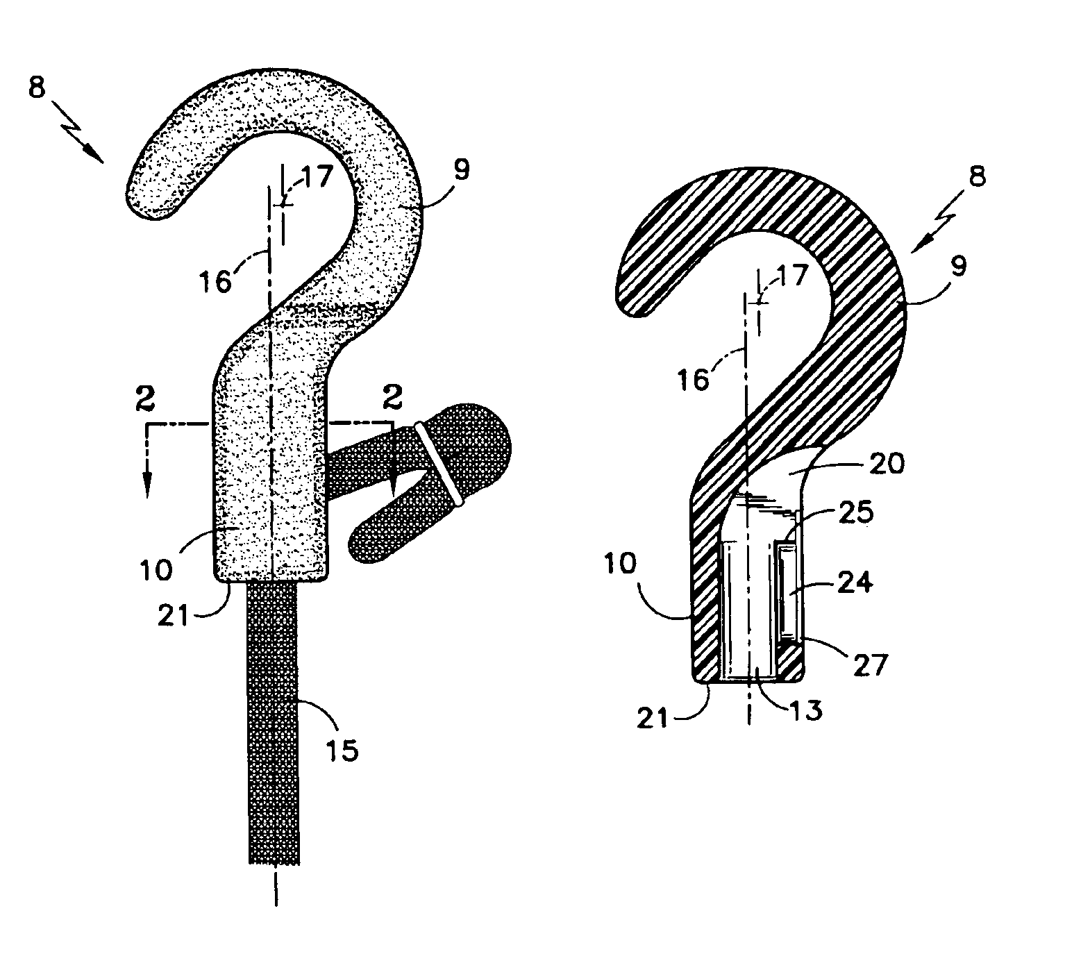
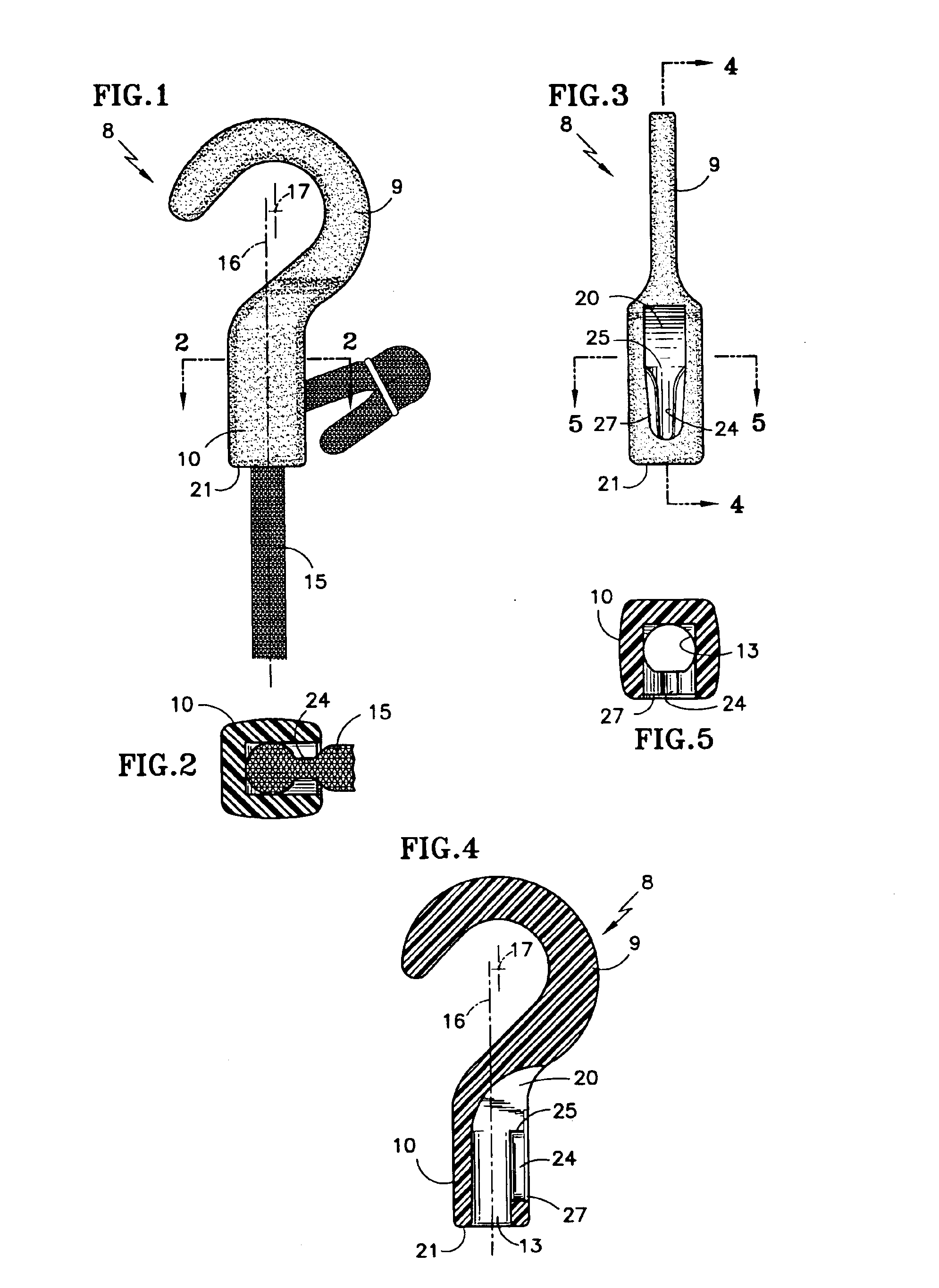
Referring to FIG. 1, the terminus 8 comprises a hook 9 integrally joined with a stem 10. The hook has a generally cylindrical shape as illustrated in FIGS. 1 and 4 and opens toward a first side (to the left in FIGS. 1 and 4) of the terminus 8. The hook 9 defines a first end of the terminus 8 and the upper end as seen in FIGS. 1, 3 and 4.

The stem 10 defines a second end of the terminus 8, the lower end in FIGS. 1, 3 and 4, and has a cord receiving bore 13 extending from the second end, the diameter being suitable to receive a stretch cord 15 with which the terminus is to be utilized. The longitudinal axis 16 of the bore 13 is within a predetermined distance of the transverse axis 17 of the hook.

A cord passage 20 extends outwardly from the bore 13 at a distance from a second end 21 of the terminus 8. A cleat 24 opens at 25 into the cord passage 20 in such a fashion that when a cord extends through the bore 13 and passage 20 it may be pulled down into the cleat 24, as illustrated in FI...


PUM


Abstract

A terminus (8) for a bungee cord (15) has a hook (9) with a transverse axis (17) which is within a given distance of the longitudinal axis (16) of a bore (13) within the stem (10) of the terminus. A cleat (24) opens into a cord passage (20) leading to the bore (13) to permit pulling a cord (15) into the cleat (24) thereby locking the terminus in position on the cord (15). The relative axial alignment of the load in the cord (15) with the transverse axis (17) of the hook (9) prevents the load (15) from rotating the hook substantially. A land (27) adjusts the thickness of the cleat.

Description

TECHNICAL FIELDThis invention relates to a terminus for stretch cord, such as may be used for tie-downs, the position of which is adjustable along the stretch cord; the parts of the terminus are so positioned that loads applied thereto by the stretch cord are transferred to substantially the center of the hook thereon.BACKGROUND ARTA widely used adjustable tie-down stretch cord is disclosed in U.S. Pat. No. 5,682,652. Therein, a terminus for the stretch cord may be positioned anywhere along the stretch cord, the stretch cord thereafter being locked into a cleat which is formed in a stem portion of the terminus. A hook extends from the opposite side of the stem for the cleat. One problem with this terminus is that axial loads imparted to the cleat, when the cord is locked therein, pull the hook in a manner which tends to cause it to rotate. Stated more simply, the load is not applied to the center of the hook. A similar result obtains in an adjustable hook for bungee cord described i...

Claims


Application Information

Patent Timeline
Patent Type & Authority Patents(United States)
IPC IPC(8): B62J7/00B62J7/08F16B45/00F16G11/00
CPCB62J7/08F16B45/00F16G11/00Y10S24/907Y10T24/45288Y10T24/314Y10T24/3918Y10T24/44701Y10T24/4755Y10T24/45262F16G11/103F16G11/143F16B45/008
Inventor SELBY, RICKY W.
Owner HAMPTON PRODS INT
Why Eureka
Try Eureka