Liner for a gas turbine engine combustor having trapped vortex cavity
- Summary
- Abstract
- Description
- Claims
- Application Information
AI Technical Summary
Problems solved by technology
Method used
Image

Examples
Embodiment Construction
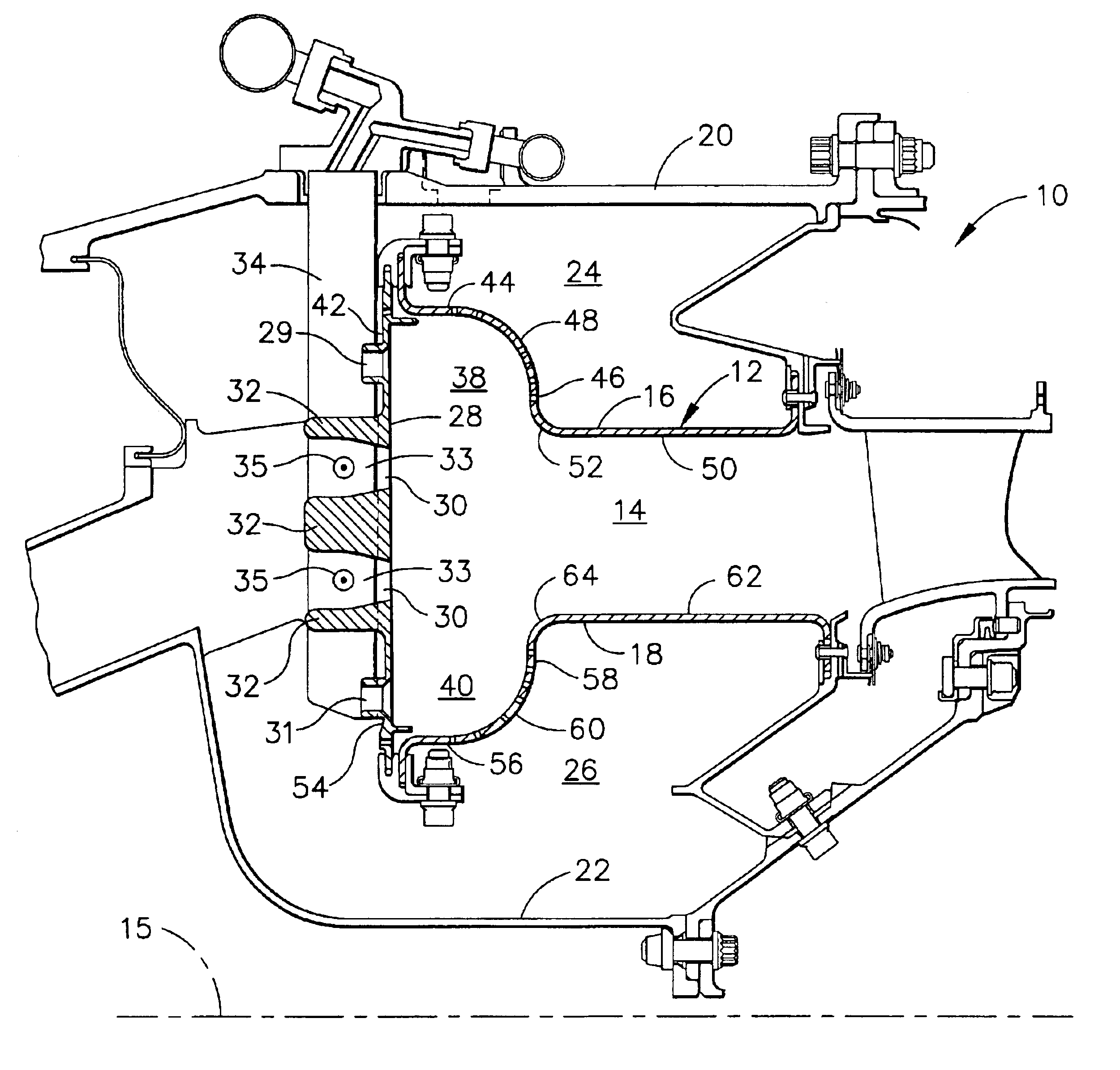
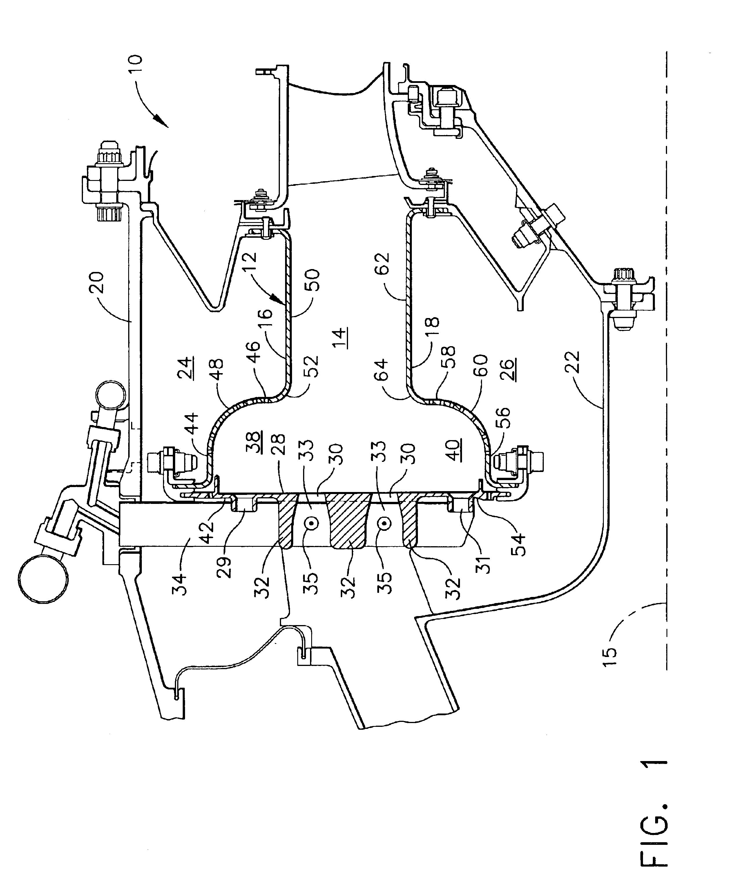
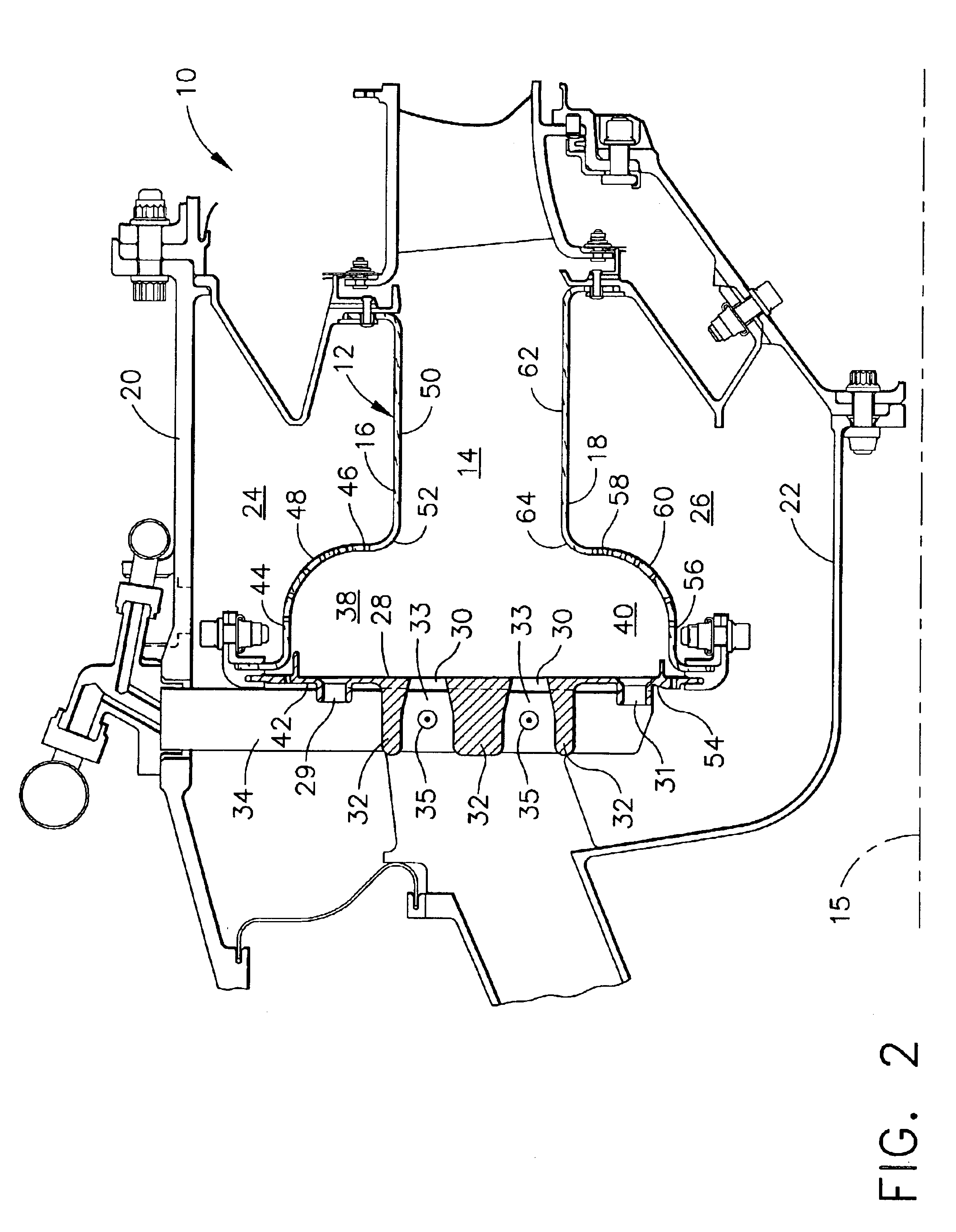
Referring now to the drawings in detail, wherein identical numerals indicate the same elements throughout the figures, FIG. 1 depicts a combustor 10 for use in a gas turbine engine which includes a hollow body 12 defining a combustion chamber 14 therein. Hollow body 12 is generally annular in form about a centerline axis 15 and includes an outer liner 16 and an inner liner 18 disposed between an outer combustor casing 20 and an inner combustor casing 22, respectively. Outer liner 16 and outer combustor casing 20 form an outer radial passage 24 therebetween, whereas inner liner 18 and inner combustor casing 22 form an inner passage 26 therebetween.
It will be appreciated that a dome plate 28 is preferably like that disclosed in U.S. Pat. No. 6,334,298 to Aicholtz, although it may be like that shown and disclosed in U.S. Pat. No. 5,619,855 to Burrus or U.S. Pat. No. 6,295,801 to Burrus et al., each of which is owned by the assignee of the current invention and is hereby incorporated by...
PUM
 Abstract
Description
Claims
Application Information