Byte alignment circuitry

a circuitry and byte technology, applied in the field of data communication, can solve the problems of difficulty or impossible for such circuitry, once aligned, to properly deal with subsequent receipt,

Inactive Publication Date: 2005-02-08
ALTERA CORP
View PDF1 Cites 60 Cited by
  • Summary
  • Abstract
  • Description
  • Claims
  • Application Information

AI Technical Summary

Problems solved by technology

A problem that can occur with known byte alignment circuitry is the following.
It is difficult or impossible for such circuitry, once aligned, to properly deal with subsequent receipt of the special byte pattern, especially if that pattern is received out of alignment with what has already been determined to be proper byte alignment.

Method used


Image

  • Byte alignment circuitry
  • Byte alignment circuitry
  • Byte alignment circuitry

Examples


Embodiment Construction

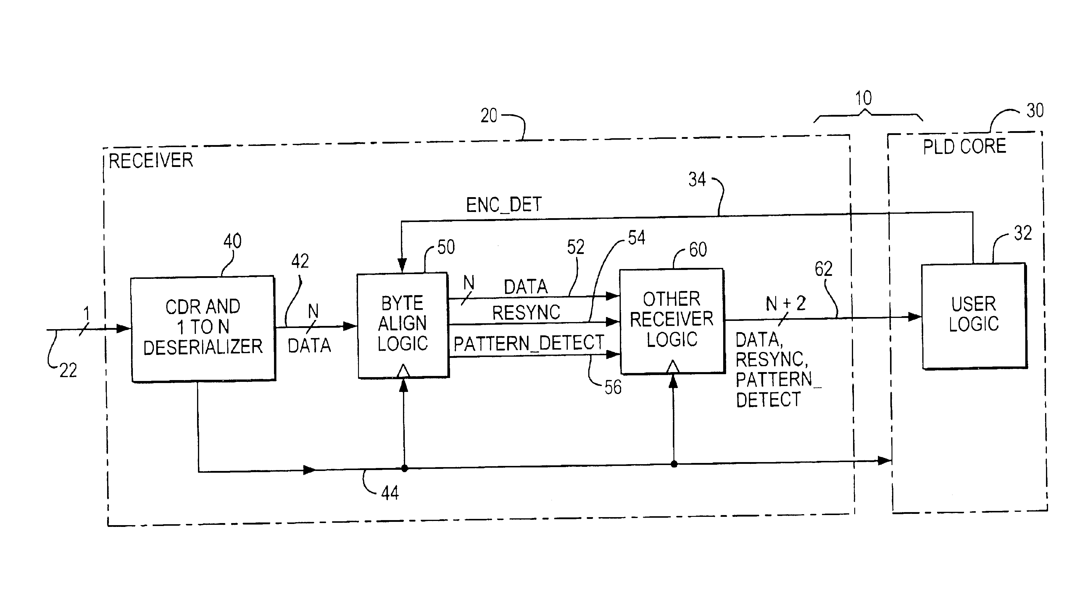
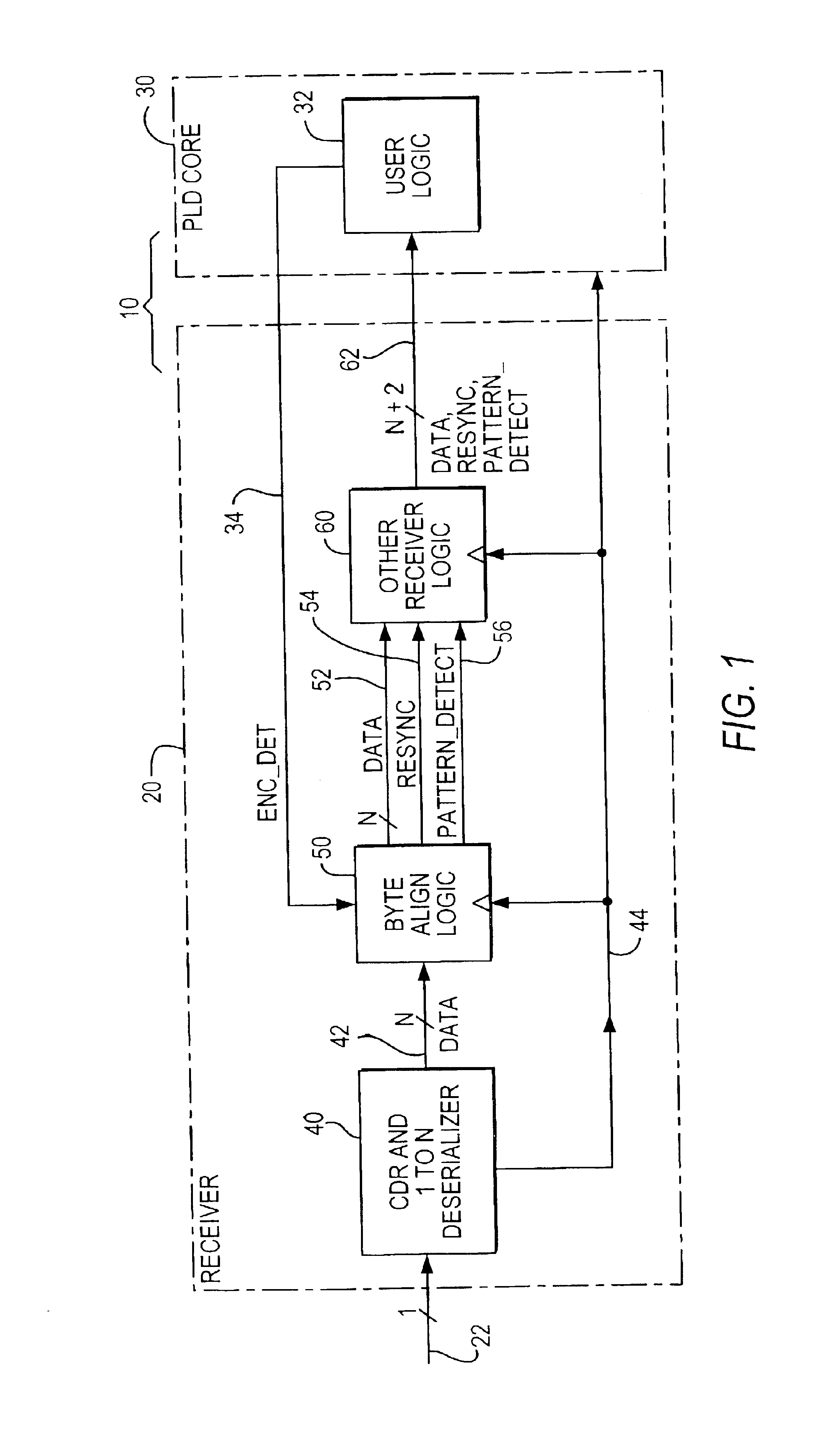
The illustrative embodiment shown in FIG. 1 is in the context of programmable logic device (“PLD”) circuitry 10 that includes receiver circuitry 20 and PLD core circuitry 30. PLD 10 is typically (although not necessarily) a single integrated circuit. (Alternatively, circuitry 10 could be, for example, a multi-chip module including two or more separate integrated circuits.) The illustrative context shown in FIG. 1 is by no means the only possible context. For example, instead of being used with PLD circuitry (like 30), receiver circuitry 20 could instead be used with many other types of utilization circuitry such as microprocessor circuitry. Many other possible contexts for the invention will occur to those skilled in the art having the benefit of the disclosure contained in this specification. The following description (e.g., of FIG. 1, etc.) will therefore be understood to be illustrative and not limiting.

Receiver 20 receives a serial bit stream signal via lead 22. This signal is a...


PUM


Abstract

Circuitry for locating the boundaries between bytes in a data stream is only selectively enabled to find a possible new byte alignment by a control signal. After the byte alignment circuitry has found a byte alignment, it outputs byte-aligned data and a first status signal indicating the presence of such data. If the byte alignment circuitry subsequently detects information that suggests a possible need for a new or changed byte alignment, it outputs a second status signal to that effect. However, the byte alignment circuitry does not actually attempt to change its byte alignment until enabled to do so by the control signal. Programmable logic circuitry or other utilization circuitry is typically provided to receive the outputs of the byte alignment circuitry and to selectively provide the control signal.

Description

BACKGROUND OF THE INVENTIONThis invention relates to data communication, and more particularly to circuitry for receiving data signals that have been communicated from a data signal source.Data is frequently transmitted serially. Typically the data represents bytes of information that are being transmitted one after another. The usual definition of a byte is eight bits, but as used herein “byte” can refer to any plural number of bits such as eight bits, nine bits, ten bits, 11 bits, or fewer or more than these numbers of bits. When the data is received, one task that the receiving circuitry must typically perform is to find the boundaries between the successive bytes in the received serial bit stream. This may be referred to as “byte alignment” or “byte synchronization”.To facilitate byte alignment, it is typical to transmit special bytes at the start of a packet of bytes of data. The receiver circuitry looks for the special byte pattern in the incoming data. When the receiver circu...

Claims


Application Information

Patent Timeline
Patent Type & Authority Patents(United States)
IPC IPC(8): G06F12/00G06F13/40H04J3/06
CPCH04J3/0608G06F13/4018
Inventor VENKATA, RAMANANDLEE, CHONG H.
Owner ALTERA CORP
Why Eureka
Try Eureka