Lock-picking prevention apparatus

a technology of prevention apparatus and lockpicking, which is applied in the direction of keyhole guards, building locks, constructions, etc., can solve the problems of many crimes relating to illegal unlocking

Inactive Publication Date: 2005-02-15
NEWING CORP +2
View PDF19 Cites 8 Cited by
  • Summary
  • Abstract
  • Description
  • Claims
  • Application Information

AI Technical Summary

Benefits of technology

is to provide a lock-picking prevention apparatus giving the same effect as providing a plurality of locks but which is merely inserted without replacing the current lock apparatus with a new one and without actually constructing a plurality of locks.

Problems solved by technology

There are therefore many crimes that occur relating to illegal unlocking of lock apparatus.

Method used


Image

  • Lock-picking prevention apparatus
  • Lock-picking prevention apparatus
  • Lock-picking prevention apparatus

Examples


first embodiment

A description will now be given, with reference to the drawings, of a lock-picking prevention apparatus of the present invention.

A “door” as referred to in this specification means a door for a house, or cover, etc., and may include a lock of a motorcycle petrol tank, etc.

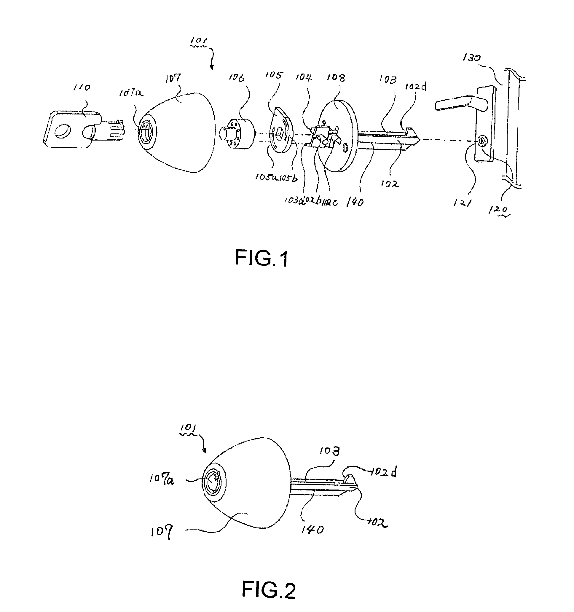
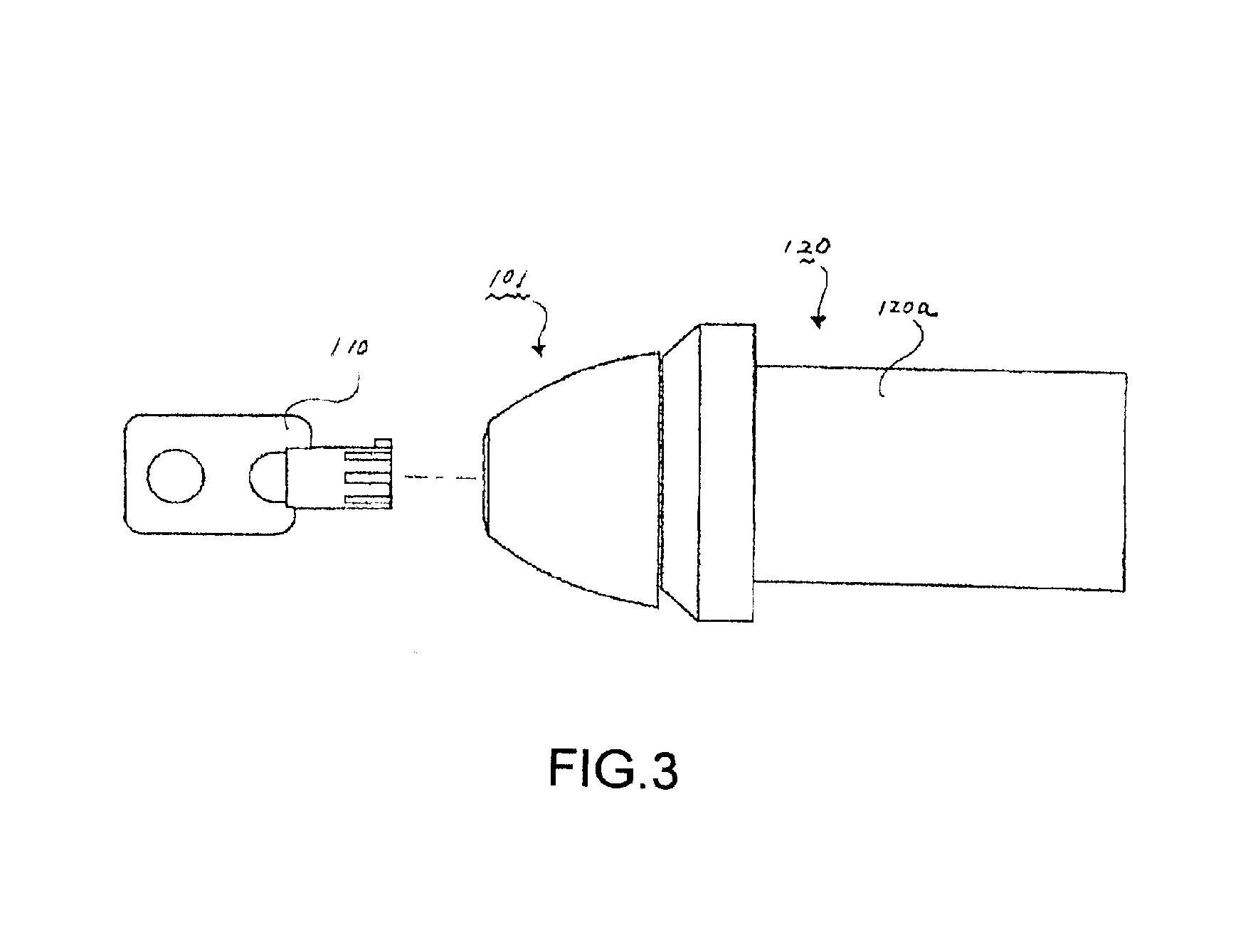
FIG. 1 is an exploded perspective view of a first embodiment of a lock-picking prevention apparatus 100. In the lock-picking prevention apparatus 101, a locking body 102 and an operating bar 103 are both arranged in the same lengthwise direction. The combination of the locking body 102 and the operating bar 103 is to be inserted into a lock hole 121 of a lock 120 mounted on a door 130.

A rotating hole 102a and a slit 102b are provided on the rear end part of the locking body 102. An operating pin 104 is connected with the curved rear end part of the operating bar 103. The operating pin 104 inserts into the rotating hole 102a. FIG. 6 is a partially exploded enlarged view of FIG. 1 showing the state where a notch 102c...

third embodiment

A description will now be given, with reference to the drawings, of a lock-picking prevention apparatus of the present invention.

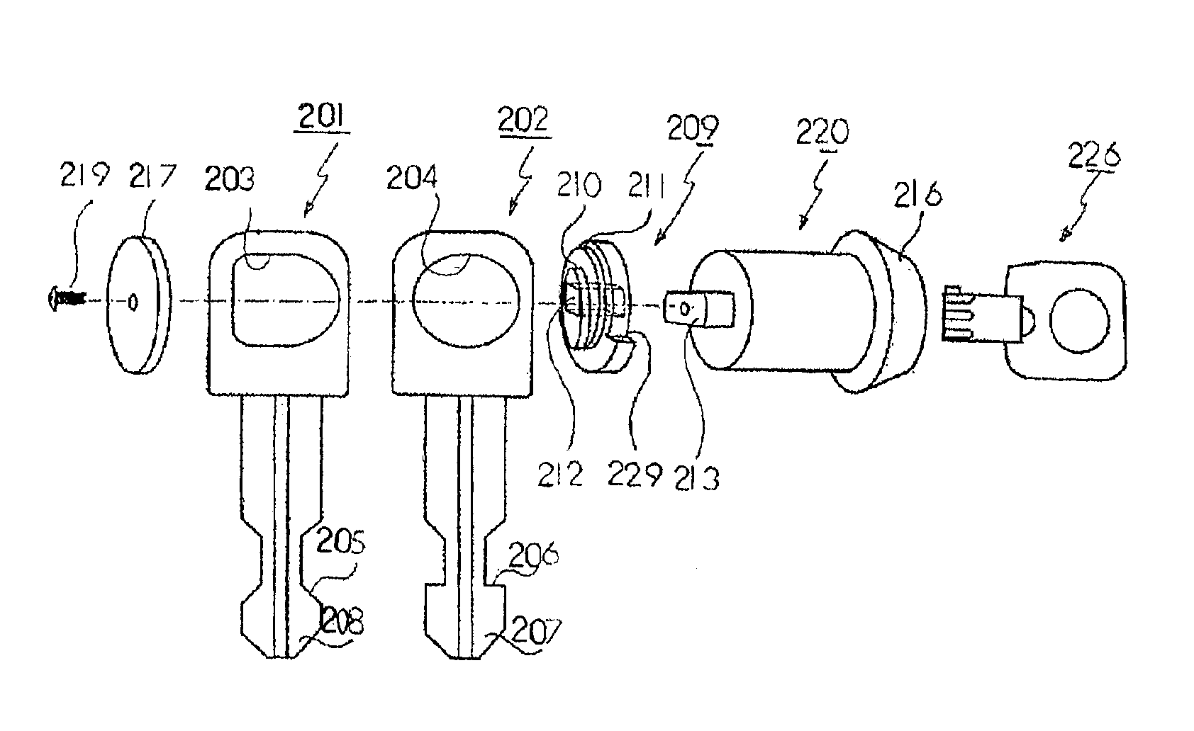
FIGS. 9A and 9B are a front view and a side view of a first locking body 201 of a third embodiment of the lock-picking prevention apparatus. FIGS. 10A and 10B are a front view and a side view of a second locking body of the third embodiment of the lock-picking prevention apparatus. FIGS. 11A to 11C are a side view, a front view, and a perspective view of an eccentric cam disk of the third embodiment of the lock-picking prevention apparatus. FIG. 12 is an exploded view of a rotating part of the third embodiment of the lock-picking prevention apparatus. FIG. 13 is a cross-sectional view of the third embodiment of the lock-picking prevention apparatus. FIG. 14A is a cross-sectional view of the state where the lock-picking prevention apparatus of the third embodiment is mounted on the door side lock, and 14B is a cross-sectional view of the state where the app...


PUM


Abstract

A lock-picking prevention apparatus is adaptable to a lock (120) having a lock hole (121) and an abutment driver pin (122) for restricting and releasing a key. The apparatus includes a locking body (102) having a front end abutment hook (102d) abutted by the abutment driver pin (122) when the lock-picking prevention apparatus is inserted into the lock hole (121) so as to bury its internal space, an operating bar (102) provided so as to slide over the abutment driver pin (122) to provide guidance, and a new key (110). At the time of unlocking using the new key (110), the operating bar (103) pushes in the abutment driver pin (122) to release the abutment of the front end abutment hook (102d) so as to enable the locking body (102) to be pulled out. The lock-picking prevention apparatus brings about a situation which is equivalent to a plurality of locks being provided.

Description

CROSS-REFERENCE TO RELATED APPLICATIONSThis patent application claims priority from Japanese Patent Application No. JP-2002-3845 U, filed on May 19, 2002, and Japanese Patent Application No. JP-2002-7287, U filed on Oct. 9, 2002.BACKGROUND OF INVENTION1. Field of the InventionThe present invention relates to a lock-picking prevention apparatus capable of being fitted simply by being inserted into an existing lock hole and providing a situation equivalent to providing a plurality of locks without actually providing a plurality of locks.The present invention relates to a lock-picking prevention apparatus preventing picking where locks are unlocked by inserting tools between a gap existing due to looseness of a cylinder bezel.2. Background ArtTypical lock apparatus are easily unlocked using a simple picking tool, etc. There are therefore many crimes that occur relating to illegal unlocking of lock apparatus. In order to prevent illegal unlocking, it is effective to change the current l...

Claims


Application Information

Patent Timeline
Patent Type & Authority Patents(United States)
IPC IPC(8): E05B17/00E05B17/16E05B17/14E05B13/02
CPCE05B17/16E05B17/142Y10S70/63Y10T70/8649Y10T70/7983
Inventor MAZZARELLO, GIANPIERO TONI
Owner NEWING CORP
Why Eureka
Try Eureka