Rigid skull fixation

a fixation pin and rigid technology, applied in the field of rigid skull fixation, can solve the problems of unstable attachment to the skull, small play between the fixation pin and the fixation pin, etc., and achieve the effect of simple and inexpensive manufacturing

Inactive Publication Date: 2011-06-30
ELEKTA AB
View PDF5 Cites 13 Cited by
  • Summary
  • Abstract
  • Description
  • Claims
  • Application Information

AI Technical Summary

Benefits of technology

[0005]Accordingly, the basis of the invention is the insight that the above object may be achieved by providing a stabilizing member, which is provided with a through opening adapted to be applied over the fixation pin in an area between the frame and the body part. On a distance from the through opening, the stabilizing member is provided with a tensioning member, which is capable to draw the stabilizing member towards the frame. Furthermore, the stabilizing device is also provided with a stop member, which is adapted to prevent displacement of the portion at the through opening along the fixation pin towards the frame when tightening the tensioning member, while at the same time the portion at the tensioning member is displaced towards the frame. This has to result that the stabilizing member will be drawn in an obliquely way in relation to the fixation pin and the frame such that the fixation pin is drawn or bent in a direction towards the tensioning member and by that the play between the fixation pin and the frame will be eliminated.
[0008]Moreover, the through opening in the stabilizing member for the fixation pin can be shaped in different ways. In one embodiment described and illustrated hereinafter, the opening is illustrated as a recess, which is open at one side of the stabilizing member and has a hook formed formation in a portion being located on an opposite side of the opening in relation to the tensioning member. In this way the mounting of the stabilizing member onto the fixation pin is facilitated and even allows mounting of the stabilizing member after the frame has been attached to a skull. In another embodiment the through opening is formed as a hole having a diameter slightly larger than the diameter of the fixation pin. Such an embodiment has to be applied on the fixation pin before attaching the frame to a skull.
[0009]An important feature of the invention is that the stabilizing member is formed with some kind of stop member which, when the stabilizing member is mounted onto the fixation pin of the frame and the tensioning member is tightened, will prevent displacement of the stabilizing member at a first position, at the through opening for the fixation pin, along the fixation pin in a direction towards the frame, while at the same time a displacement of a second position, at the tensioning member, towards the frame is allowed. Such a stop member can be realized in many different ways and examples will be described more in detail in connection with hereinafter described and illustrated embodiments of the invention. A common feature with all of the embodiments is that when tightening the tensioning member, the first position of the stabilizing member will be slightly drawn towards the frame such that the stabilizing member including the through opening around the fixation pin, will be inclined in relation to the fixation pin such that the fixation pin will be drawn and / or bent towards the tensioning member which will eliminate any play between the fixation pin and the frame.

Problems solved by technology

However, a small play is always present between each fixation pin and the frame even if it is tried to obtain a tight fit.
Such a play will make the attachment to the skull unstable and will have an especially large influence on the position of the frame in relation to the head in a case where the distance from the frame to the skull is very long, due to for example fixation to a small skull, such as a skull of a child where very long fixation pins have to be used.

Method used


Image

  • Rigid skull fixation
  • Rigid skull fixation
  • Rigid skull fixation

Examples


first embodiment

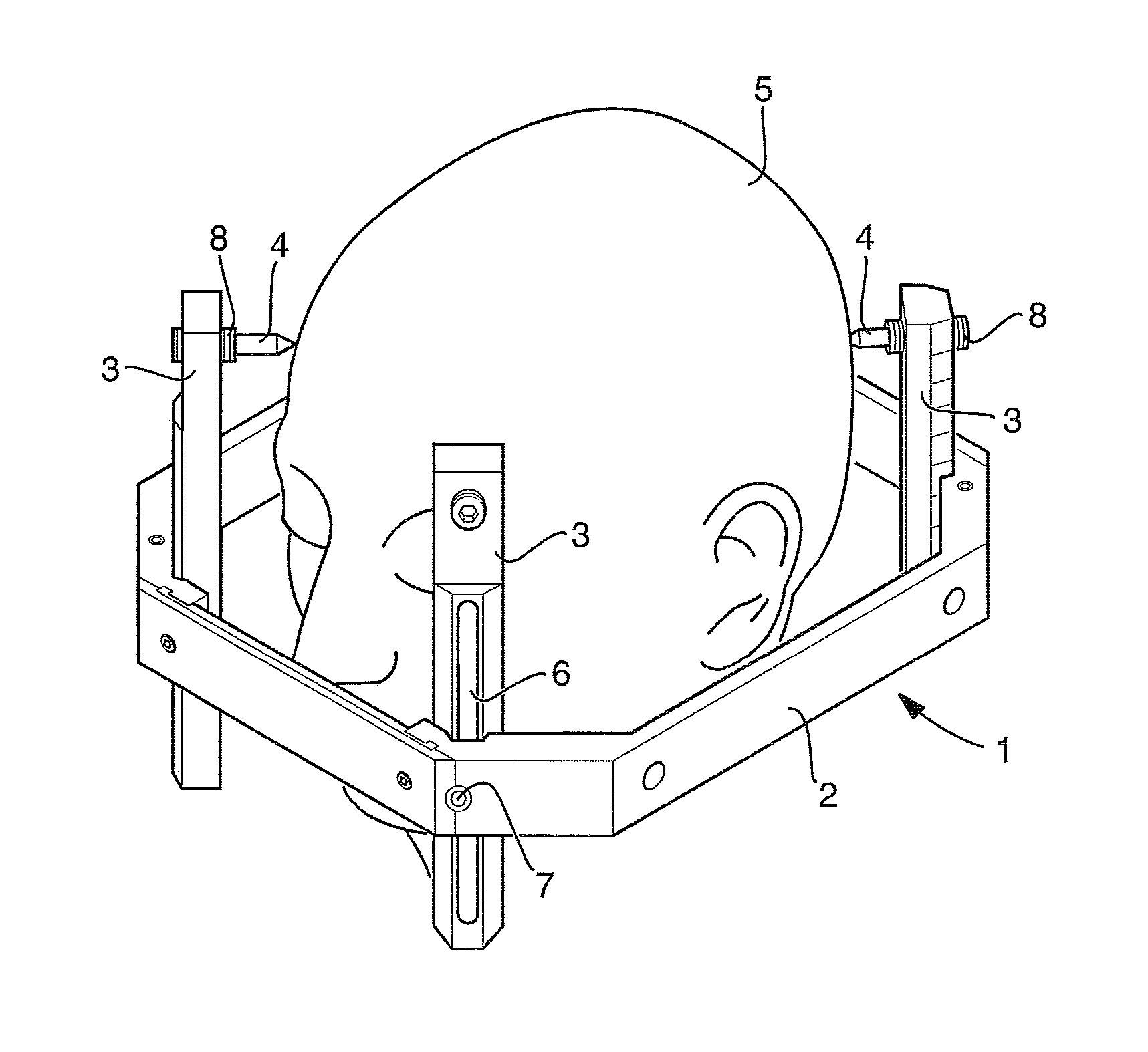
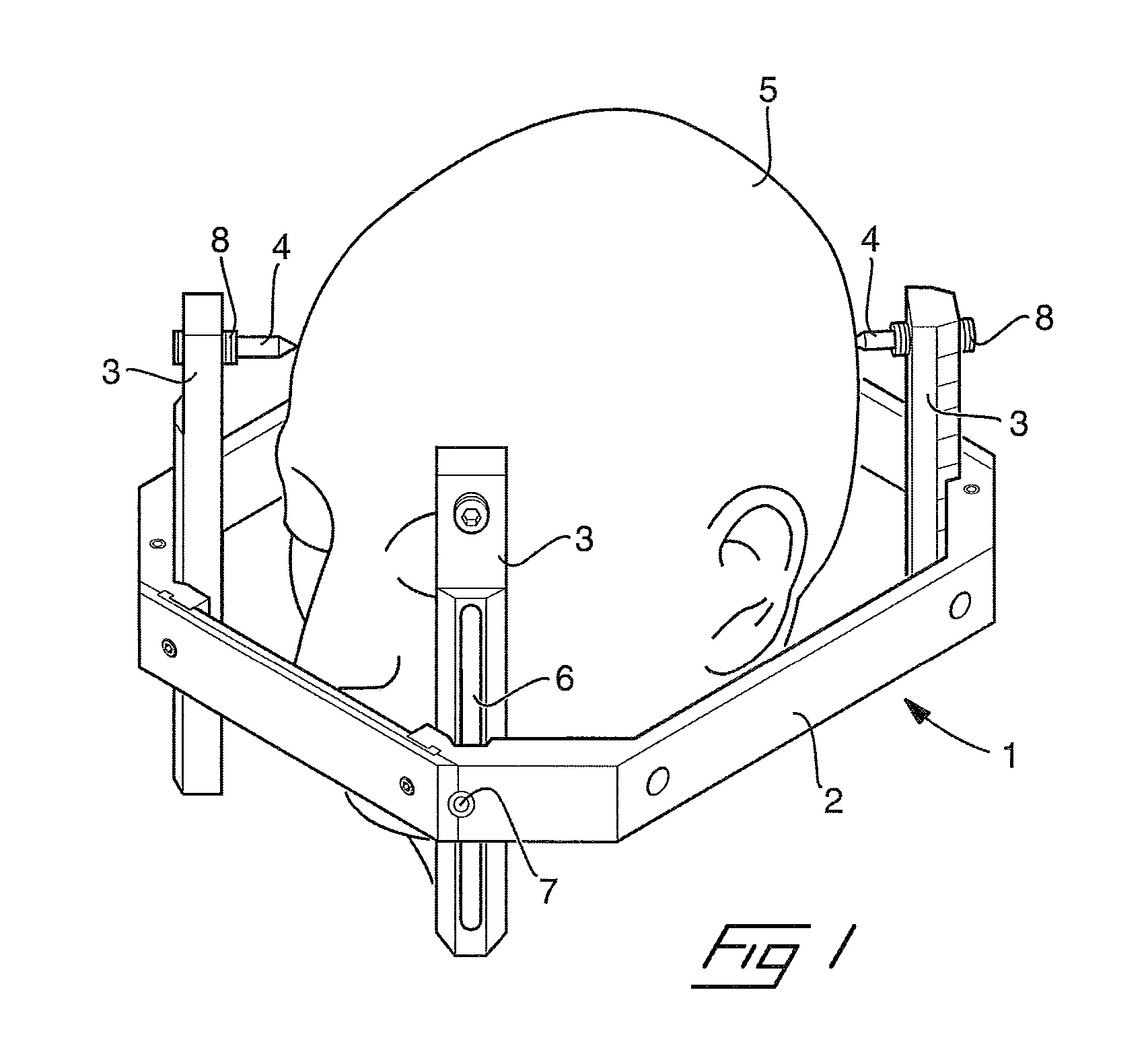
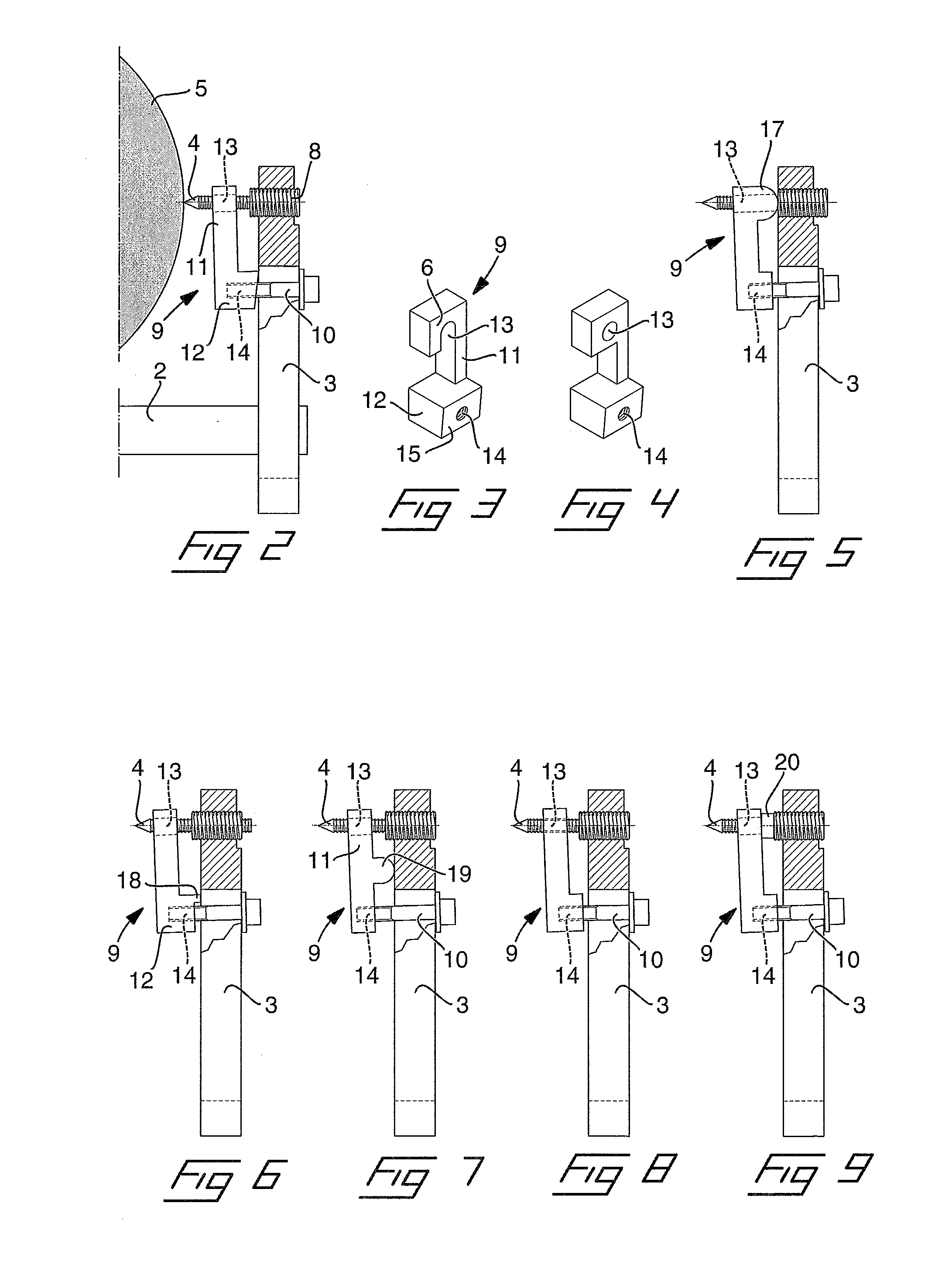
[0018]Reference is then made to FIG. 2 in which is illustrated a part of the stereotactic frame, including the annular support structure 2 and the post 3, and a fixation pin 4 being screwed into the skull 5 of a patient, and a stabilizing device, according to the invention, which is mounted to stabilize the fixation pin in relation to the post. The stabilizing device comprises a stabilizing member 9 and a tensioning member 10 in form of a screw having an external thread. The stabilizing member 9 is in form of a rigid body comprising an upright portion 11 and a laterally directed projection 12 in the lower end portion of the stabilizing member. A through opening 13 for the fixation pin 4 is formed in the upper end portion of the stabilizing member and a hole 14 having an internal thread for the tensioning screw is formed in the projection 12. An end surface 15 of the projection, which in the mounted state, as shown in FIG. 2, is adapted to bear against the post 3, is inclined and pre...

second embodiment

[0020]FIG. 5 illustrates the inventive stabilizing device. Here the stop member is formed as a projection 17 located at the area of the through opening 13 for the fixation pin and extending in the direction towards the post and has a rounded end surface. When tightening the tensioning screw, the projection will prevent displacement of the first position of the stabilizing member around the through opening for the fixation pin, while the second position of the stabilizing member around the threaded hole 14 for the tensioning screw will be drawn towards the post 3. In this way the fixation pin will be drawn and / or bent downwards such that the play between the fixation pin and the post will be eliminated.

[0021]A third embodiment of the stabilizing device, which is illustrated in FIG. 6, is similar to the first embodiment according to FIG. 2. However, here the end surface of the projection 12 is not inclined as in the first embodiment. Instead, the end surface is provided with a ridge i...

fourth embodiment

[0022]the stabilizing device is illustrated in FIG. 7. Here, the stabilizing member is in form of an upright portion 11 having a projection 19, at an intermediary position between the through opening 13 and the threaded hole 14 for the tensioning screw 10, which is directed towards the post 3 and has a rounded end surface. The projection 19 will function as a stop member which, when the tensioning screw is tightened, will prevent displacement of the first position around the through opening for the fixation pin towards the post, but will allow displacement of the second position around the threaded hole for the tensioning screw towards the post. Accordingly, the fixation pin 4 will be drawn / bent towards the tensioning screw eliminating any play between the fixation pin and the post.


PUM


Abstract

The invention relates to a stabilizing device adapted to be applied to a stereotactic frame (2, 3), which is provided with fixation pins (4) to allow fixation of the stereotactic frame to a bone (5) of a human or animal body part to be examined or treated, wherein the stabilizing device is adapted to stabilize a fixation pin in relation to the frame. The stabilizing device comprises a stabilizing member (9) which in a first position is provided with a through opening (13), adapted to be applied over the fixation pin in an area between the frame and the body part, and a tensioning member (10) positioned in a second position on a distance from the through opening and being capable of drawing the stabilizing member towards the frame. The stabilizing member is formed with a stop member (12), which is adapted, when tightening the tensioning member, to prevent displacement of the first position of the stabilizing member along the fixation pin towards the frame, while allowing displacement of the second position of the stabilizing member towards the frame, such that the fixation pin will be drawn or bent in a direction towards the second position.

Description

[0001]The present invention relates to a stabilizing device adapted to be applied to a stereotactic frame, which is provided with fixation pins to allow fixation of the stereotactic frame to a bone of a human or animal body part to be examined or treated, wherein the stabilizing device is adapted to stabilize a fixation pin in relation to the frame.BACKGROUND OF THE INVENTION[0002]A stereotactic frame is used for establishing a reference system to localize areas to be treated during imaging such as MRI-scanning of a head of a patient and / or for supporting instruments during neurological surgery, therapy or diagnosis. The stereotactic frame is arranged around the head and fixation pins connected to the frame are screwed into or to abutment against the bone of the skull to ensure a rigid fixation of the reference system.[0003]However, a small play is always present between each fixation pin and the frame even if it is tried to obtain a tight fit. Such a play will make the attachment t...

Claims


Application Information

Patent Timeline
Patent Type & Authority Applications(United States)
IPC IPC(8): A61B17/00
CPCA61B19/203A61B90/14
Inventor ARN, THOMAS
Owner ELEKTA AB
Why Eureka
Try Eureka