Cup holder device

a cup holder and cup holder technology, applied in the direction of aircraft crew accommodation, machine supports, washstands, etc., can solve problems such as friction, and achieve the effects of reducing manufacturing costs, improving assembly process, and reducing the number of members

Inactive Publication Date: 2005-01-04
NIFCO INC
View PDF7 Cites 12 Cited by
  • Summary
  • Abstract
  • Description
  • Claims
  • Application Information

AI Technical Summary

Benefits of technology

is to provide a cup holder device as stated above, which can reduce the manufactu

Problems solved by technology

The first supporting link pushes the tray throug

Method used


Image

  • Cup holder device
  • Cup holder device
  • Cup holder device

Examples


Embodiment Construction

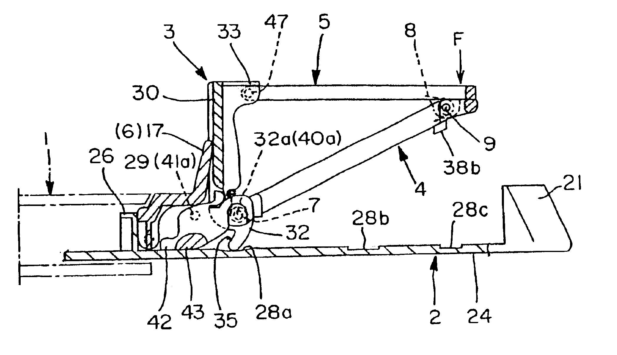
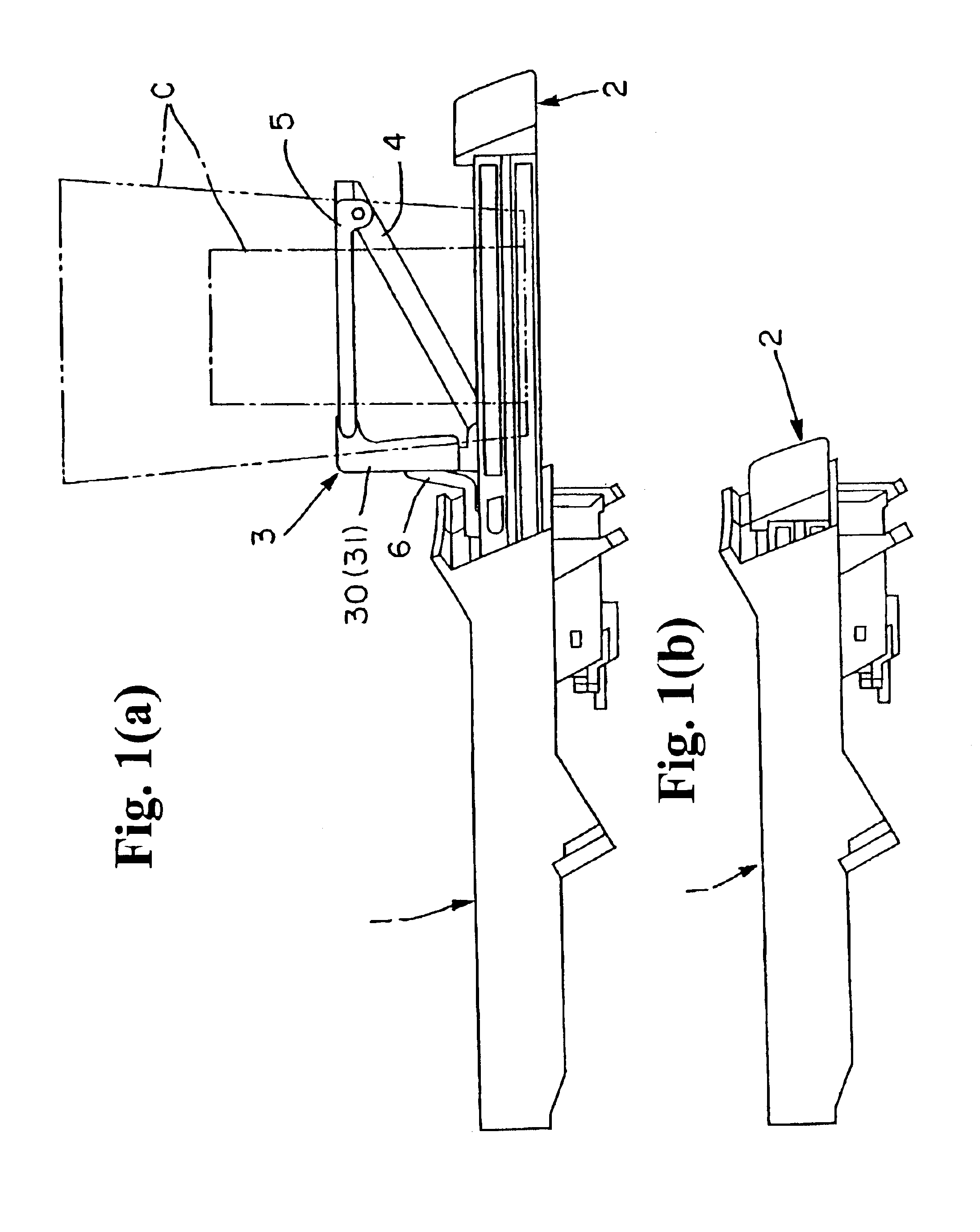
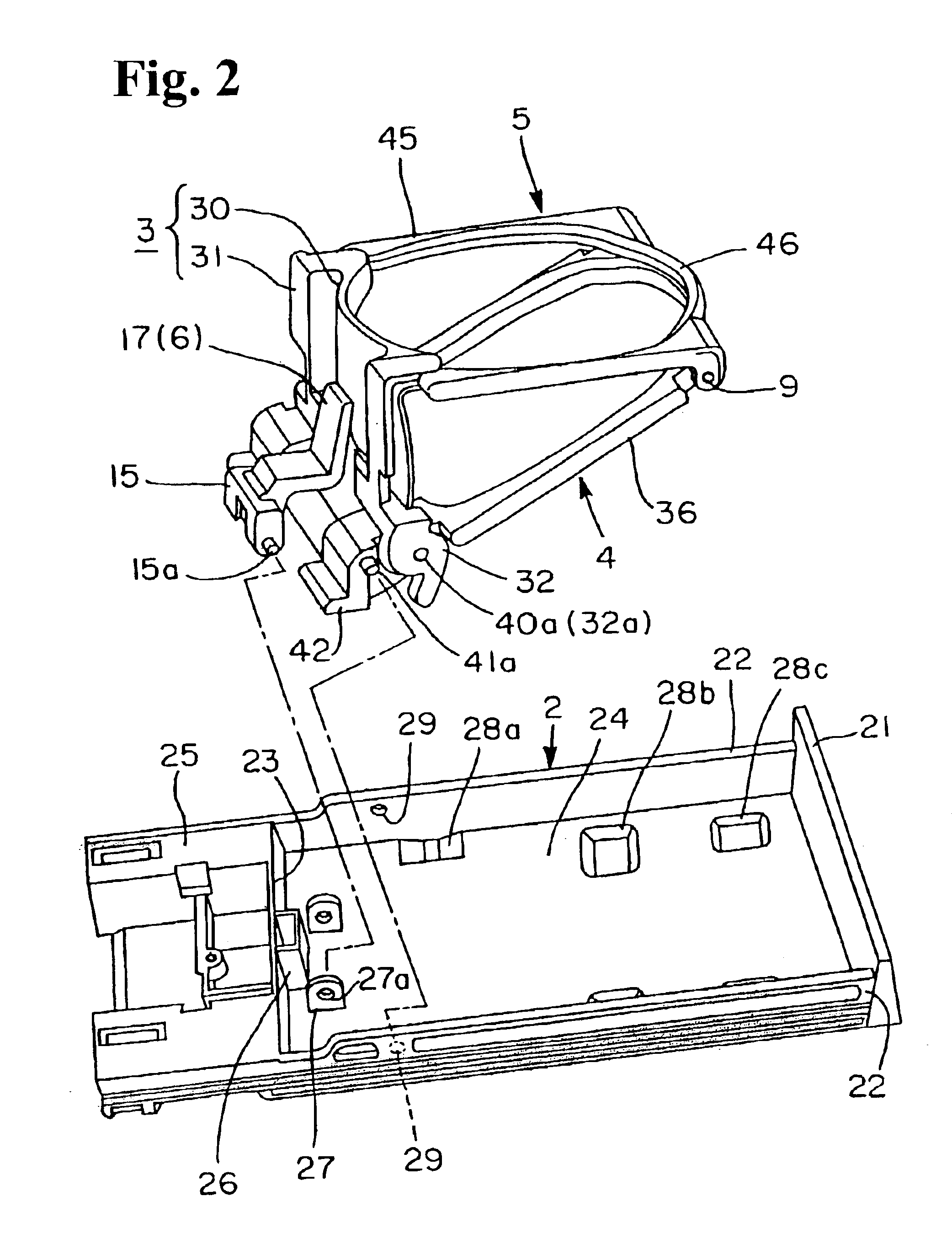
Hereunder, embodiments of the present invention will be explained with reference to the accompanying drawings. FIGS. 1(a)-1(b) to FIGS. 8(a)-8(c) are views showing a cup holder device according to the present invention. FIGS. 1(a)-1(b) are side views showing the cup holder device, wherein FIG. 1(a) is a side view showing a pullout position where the tray is pulled out, and FIG. 1(b) is a side view showing a stored position where the tray is pushed in. FIG. 2 is a view showing a relationship between supporting links, assembling members of a holder, and a tray of the cup holder device. FIG. 3 is an exploded view showing a relationship between the supporting links and the holder. FIGS. 4(a)-4(b) are views showing an operation of the cup holder device, wherein FIG. 4(a) is a cross sectional view showing the pullout position where the tray is pulled out, and FIG. 4(b) is a cross sectional view showing a state where the tray is slightly moved to the stored position.

FIGS. 5(a)-5(f) are vie...


PUM


Abstract

A cup holder device includes a case; a tray movable between a stored position and a pullout position; first and second supporting links movable upward with an urging force around base ends; and a holder. A front end of the holder is rotatably connected to the second supporting link, and a rear end of the holder is connected to the first supporting link to slide freely. The holder moves between a non-use position where the holder is stored in the tray and a use position where the holder moves up from the tray. The first supporting link includes projected parts projecting at edges of base ends. When the first and second supporting links move upward, the projected parts are arranged to move to contact the tray and push the tray with a gradually increasing force.

Description

BACKGROUND OF THE INVENTION AND RELATED ART STATEMENTThe present invention relates to a pullout type cup holder device equipped inside a vehicle, ship, or aircraft for holding a container such as a can, cup, or drink box of beverage.A pullout type cup holder device is installed in, for example, an instrument panel of a vehicle, and an occupant pulls out the holder for holding a periphery of a container as needed. The pullout type holder includes an uprising type in which the holder stands upward relative to a tray and a suspensory type in which the holder lowers relative to a tray.FIGS. 9(a)-(b) show two conventional uprising type devices disclosed in Japanese Patent Publications (Tokkai) No. 8-26013 and No. 2001-347874. Both devices include trays 51, 61 which is able to switch between a stored position and a pullout position relative to cases 50, 60; and holders 52, 62 which is able to switch between a non-use position stored in the trays 51, 61 at the stored position and in a use ...

Claims


Application Information

Patent Timeline
IPC IPC(8): B60N3/10B60N3/00
CPCB60N3/102B64D11/0638B60N3/106Y10S224/926B60N3/10
Inventor IZUME, TOMOHARU
Owner NIFCO INC
Why Eureka
Try Eureka