Haptic feedback system and method

a haptic feedback and feedback technology, applied in the field of haptic feedback systems and methods, can solve the problems of difficult operation of control knobs, poor haptic feedback provided by such prior art systems, and give such knobs a “cheap” feel, and achieve the effect of preventing corrosion

Active Publication Date: 2009-01-15
TOUCHSENSOR TECH
View PDF28 Cites 12 Cited by
  • Summary
  • Abstract
  • Description
  • Claims
  • Application Information

AI Technical Summary

Benefits of technology

[0008]The present invention provides haptic feedback using a magnetic “detent” mechanism. A preferred embodiment of a rotary knob assembly having haptic feedback according to the present invention includes a movable portion, for example, a wheel attached to a shaft. The wheel can include a number of ferrous elements c...

Problems solved by technology

The tactile feedback provided by such prior art systems is less than ideal in at least some circumstances, particularly with respect to the inherent play and/or the discontinuo...

Method used


Image

  • Haptic feedback system and method
  • Haptic feedback system and method
  • Haptic feedback system and method

Examples


Embodiment Construction

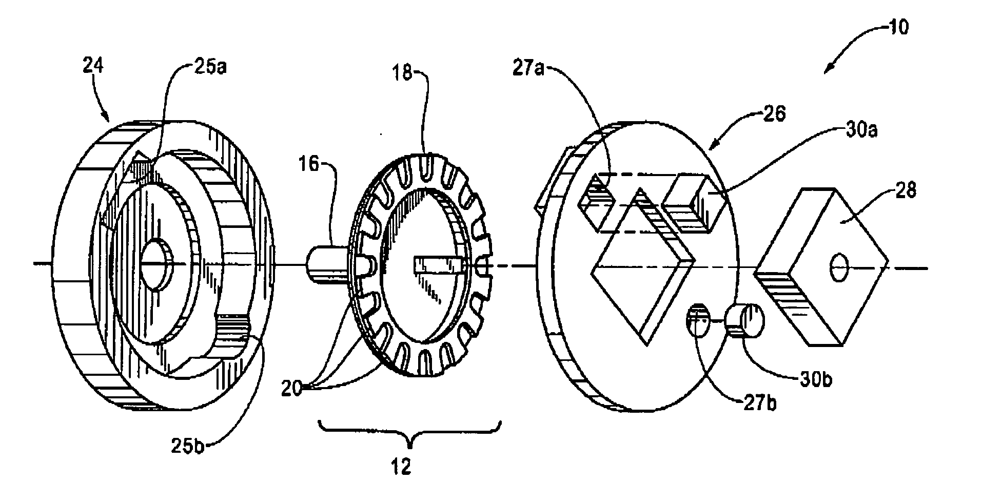
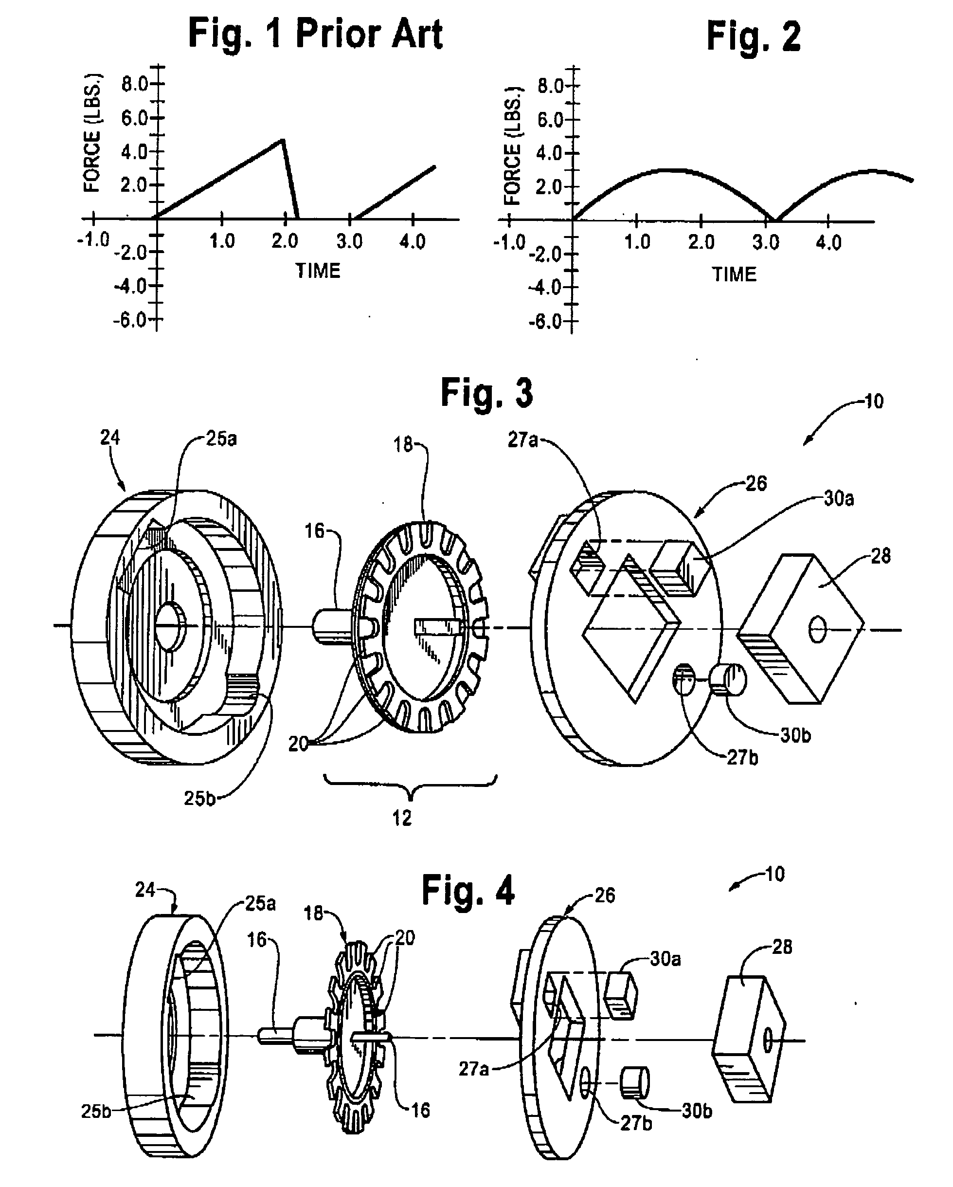
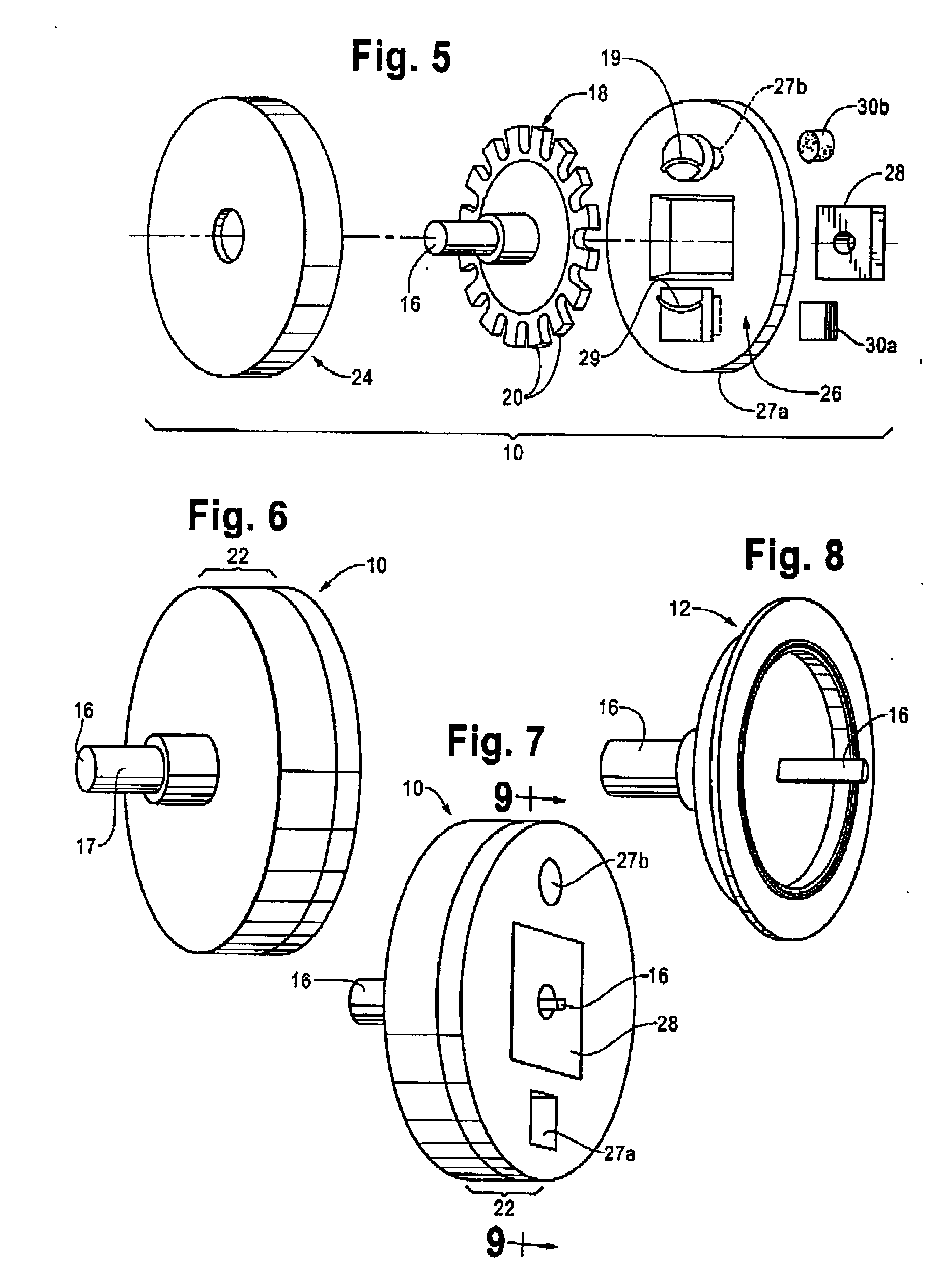
[0031]FIGS. 3-9 and 19 illustrate certain preferred embodiments of a self-contained rotary knob assembly 10 having a haptic feedback system according to the present invention. Assembly 10 includes movable portion 12 comprising knob 14 attached to one end of shaft 16. Shaft 16, in turn, is attached to wheel 18 having a number of ferrous elements 20 which preferably are located near or about the perimeter of wheel 18. As illustrated in, for example, FIG. 3, wheel 18 and ferrous elements 20 can be embodied as a disc with ferrous elements formed therein, or inlaid, embedded, adhered, or otherwise attached to or about the perimeter thereof. As illustrated in, for example, FIG. 5, wheel 18 and ferrous elements 20 can be embodied as a cog having a number of teeth formed about its perimeter. Wheel 18 and ferrous elements 20 could be embodied in other forms, as well. Although the illustrated embodiments include certain numbers of ferrous elements 20 associated with and closely (and evenly) s...


PUM


Abstract

A haptic feedback system includes movable and static portions coupled by one or more magnetic fields that serve to retard movement of the movable portion with respect to the static portion so as to provide haptic feedback when the movable portion is moved relative to the static portion. A magnet associated with one of the movable and static portions reacts with structure associated with the other of the movable and static portions so as to provide haptic feedback when the movable portion is moved with respect to the static portion.

Description

CROSS REFERENCE TO RELATED APPLICATIONS[0001]This application claims priority from U.S. Provisional Patent Application No. 60 / 894,355, filed on Mar. 12, 2007, the disclosure of which is hereby incorporated by reference.BACKGROUND OF THE INVENTION[0002]1. The Technical Field[0003]The present invention relates generally to systems and methods for providing haptic feedback in connection with, for example, rotary knobs, sliders, and the like.[0004]2. The Related Art[0005]It is known to incorporate a mechanical detent mechanism with a rotary knob to provide the user with tactile feedback regarding the movement and relative position of the knob. Such detent mechanisms typically establish one or more predetermined detent positions toward which the mechanism biases the knob. Typically, some amount of play or slop is associated with each detent such that the biasing force does not precisely center the knob within the detent. Such systems are commonly found in radio and appliance controls.[00...

Claims


Application Information

Patent Timeline
IPC IPC(8): H01F7/00
CPCG06F3/0362G06F3/016G05G5/06G05G1/08
Inventor NORTH, JOHNSTAMBAUGH, DERON
Owner TOUCHSENSOR TECH
Why Eureka
Try Eureka