Fixed type constant velocity universal joint

a constant velocity, universal joint technology, applied in the direction of yielding couplings, couplings, rotary machine parts, etc., can solve the problems of lowering the durability life of the joint at high angle and high load, and achieve the effect of lowering the durability life of the joint, high load, and high angl

Active Publication Date: 2005-04-14
NTN CORP
View PDF4 Cites 13 Cited by
  • Summary
  • Abstract
  • Description
  • Claims
  • Application Information

AI Technical Summary

Benefits of technology

[0008] In a fixed type constant velocity universal joint, when torque is transmitted in a state of forming a working angle, in the cage pockets, the balls move in the circumferential direction, and also move in the radial direction at the same time (see FIG. 1). In the conventional fixed type constant velocity universal joint of six balls, the wall thickness of the cage has been determined to set

Problems solved by technology

This is because increase of wall thickness of the cage causes the depth of guide grooves in the outer and

Method used


Image

  • Fixed type constant velocity universal joint
  • Fixed type constant velocity universal joint
  • Fixed type constant velocity universal joint

Examples


Embodiment Construction

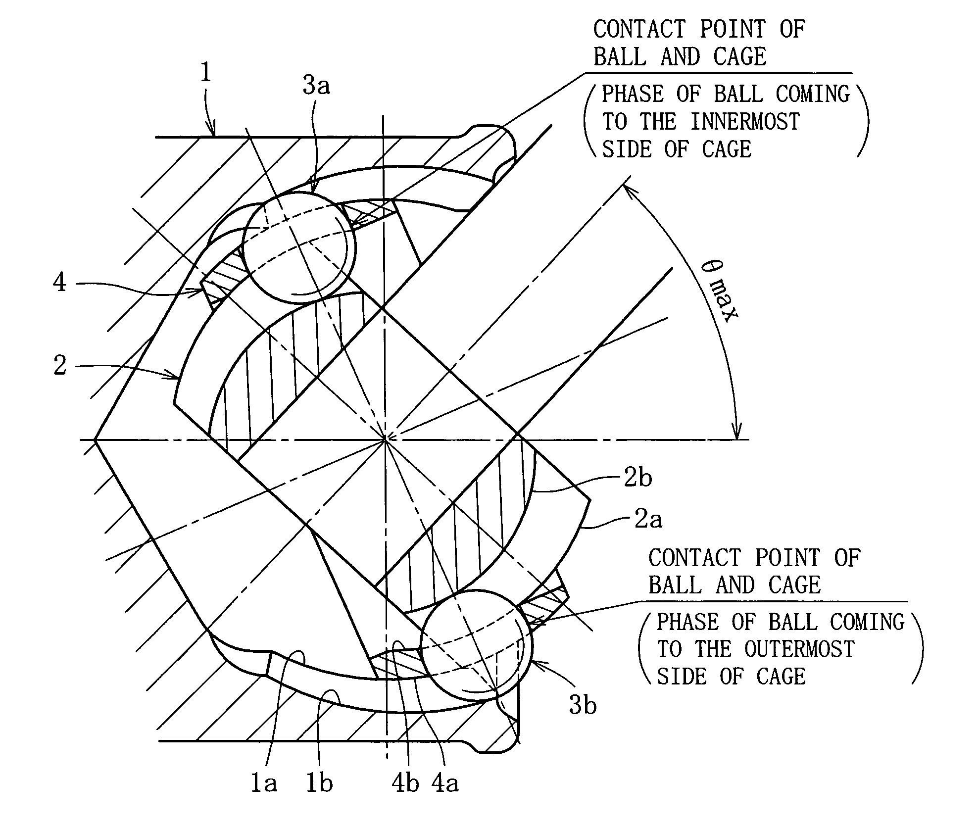
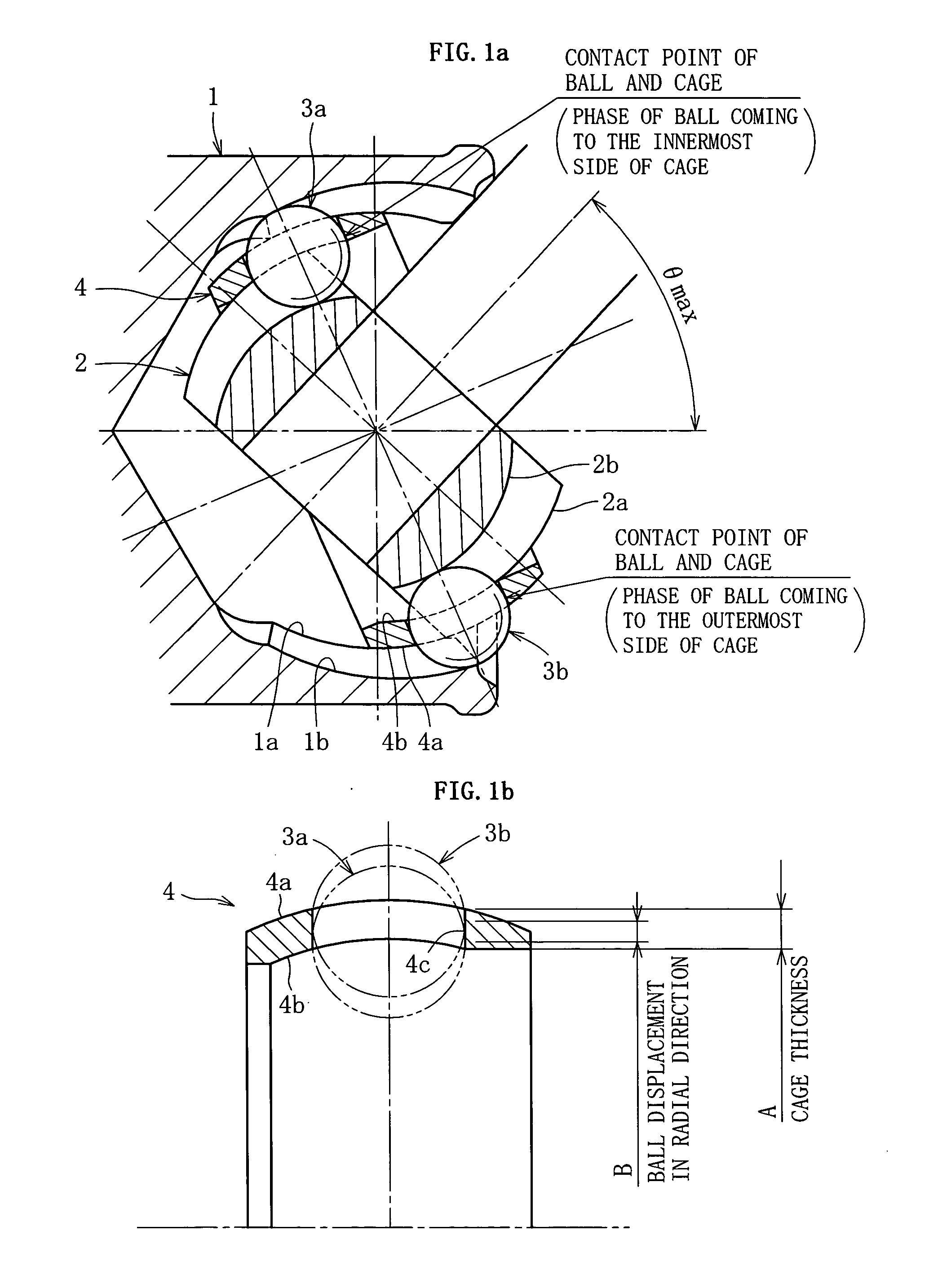
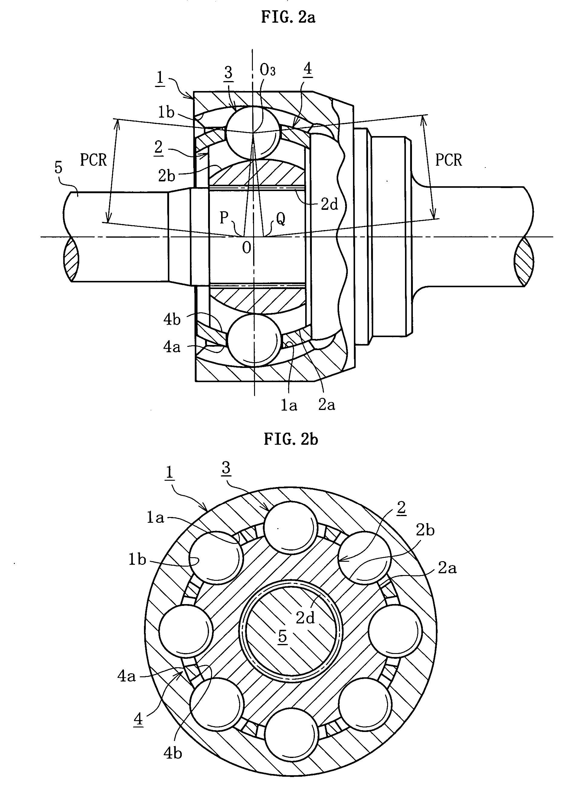
[0031] First, an embodiment of BJ type shown in FIGS. 2a, 2b and FIG. 3 is explained. FIG. 2a is a longitudinal sectional view of a joint, and FIG. 2b is a cross-sectional view of the joint. FIG. 3 is a partial, magnified view of FIG. 2a.

[0032] As shown in FIGS. 2a, 2b and 3, the fixed type constant velocity universal joint is mainly composed of an outer ring 1, an inner ring 2, balls 3, and a cage 4. The outer ring 1 as outer joint member is formed like a cup, and a shaft part for connecting with one of two shafts to be coupled is formed at the closed end side thereof. The outer ring 1 has a spherical inner circumference, that is, an inner spherical surface 1a, and eight arcuate guide grooves 1b extending in the axial direction are formed in the inner spherical surface 1a. The inner ring 2 as inner joint member has a tooth profile, i.e. serration or spline, 2d to be connected with other one (shaft part 5) of two shafts to be coupled. The inner ring 2 has a spherical outer circumfe...


PUM


Abstract

A fixed type constant velocity universal joint comprising an outer joint member (1) having eight arcuate guide grooves (1b) extending in the axial direction in an inner spherical surface (1a), an inner joint member (2) having eight arcuate guide grooves (2b) extending in the axial direction in an outer spherical surface (2a), eight balls (3) disposed between the guide grooves (1b) of the outer joint member (1) and guide grooves (2b) of the inner joint member (2), and a cage (4) interposed between the outer and inner joint members (1) and (2) for retaining the balls (3), in which center (P) of guide grooves (1b) of the outer joint member (1) is offset from center (O) of inner spherical surface (1a), and center (Q) of guide grooves (2b) of the inner joint member (2) is offset from center (O) of outer spherical surface (2a) by equal distance (PO=QO=F) to opposite sides in the axial direction, and the relation of 0.45≦B/A≦0.65 is established, where A stands for the wall thickness of the cage (4), and B the radial displacement of balls 3 at maximum joint angle.

Description

BACKGROUND OF THE INVENTION [0001] 1. Field of the Invention [0002] The present invention relates to a constant velocity universal joint used in power transmission in automobiles and various industrial machines, and more particularly to a fixed type constant velocity universal joint having eight balls. [0003] 2. Prior Art [0004] Constant velocity universal joints are classified into a fixed type not sliding in the axial direction, and a slidable type. FIGS. 8a and 8b show a Rzeppa type constant velocity universal joint (hereinafter called BJ type) as a representative example of fixed type constant velocity universal joint. This constant velocity universal joint comprises an outer ring 11 as an outer joint member having six arcuate guide grooves 11b extending in the axial direction in an inner spherical surface 11a, an inner ring 12 as an inner joint member having six arcuate guide grooves 12b extending in the axial direction in an outer spherical surface 12a, six balls 13 disposed b...

Claims


Application Information

Patent Timeline
IPC IPC(8): F16D3/223F16D3/2237F16D3/224F16D3/2245
CPCF16D3/223F16D3/2237Y10S464/906F16D2003/22303F16D2003/22309F16D3/2245
Inventor KOBAYASHI, MASAZUMINAKAGAWA, TOHRUKOBAYASHI, TOMOSHIGENAKAMURA, MASAMICHI
Owner NTN CORP
Why Eureka
Try Eureka