Air-assisted air valve for air atomized spray guns

Inactive Publication Date: 2005-02-15
CARLISLE FLUID TECH INC
View PDF13 Cites 46 Cited by
  • Summary
  • Abstract
  • Description
  • Claims
  • Application Information

AI Technical Summary

Benefits of technology

According to an aspect of the invention, a coating material dispensing device includes a port adapted to be coupled to a source of coating material, an actuator for controlling a flow of compressed gas or mixture of gases (hereinafter sometimes “compressed gas” or “gas”) through the dispensing device, and a valve coupled to the actuator to be controlled by the actuator. The valve includes a valve housing, a valve closure member, and a valve seat. The valve closure member is movable in the housing under the control of the actuator between a closed position against the valve seat and an open position away from the valve sea

Problems solved by technology

No representation is intended by this listing that a thorough search of all materia

Method used


Image

  • Air-assisted air valve for air atomized spray guns
  • Air-assisted air valve for air atomized spray guns
  • Air-assisted air valve for air atomized spray guns

Examples


Embodiment Construction

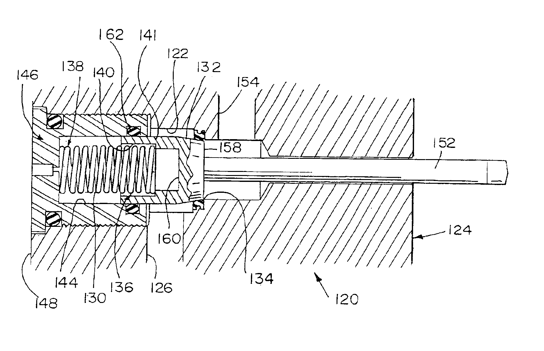
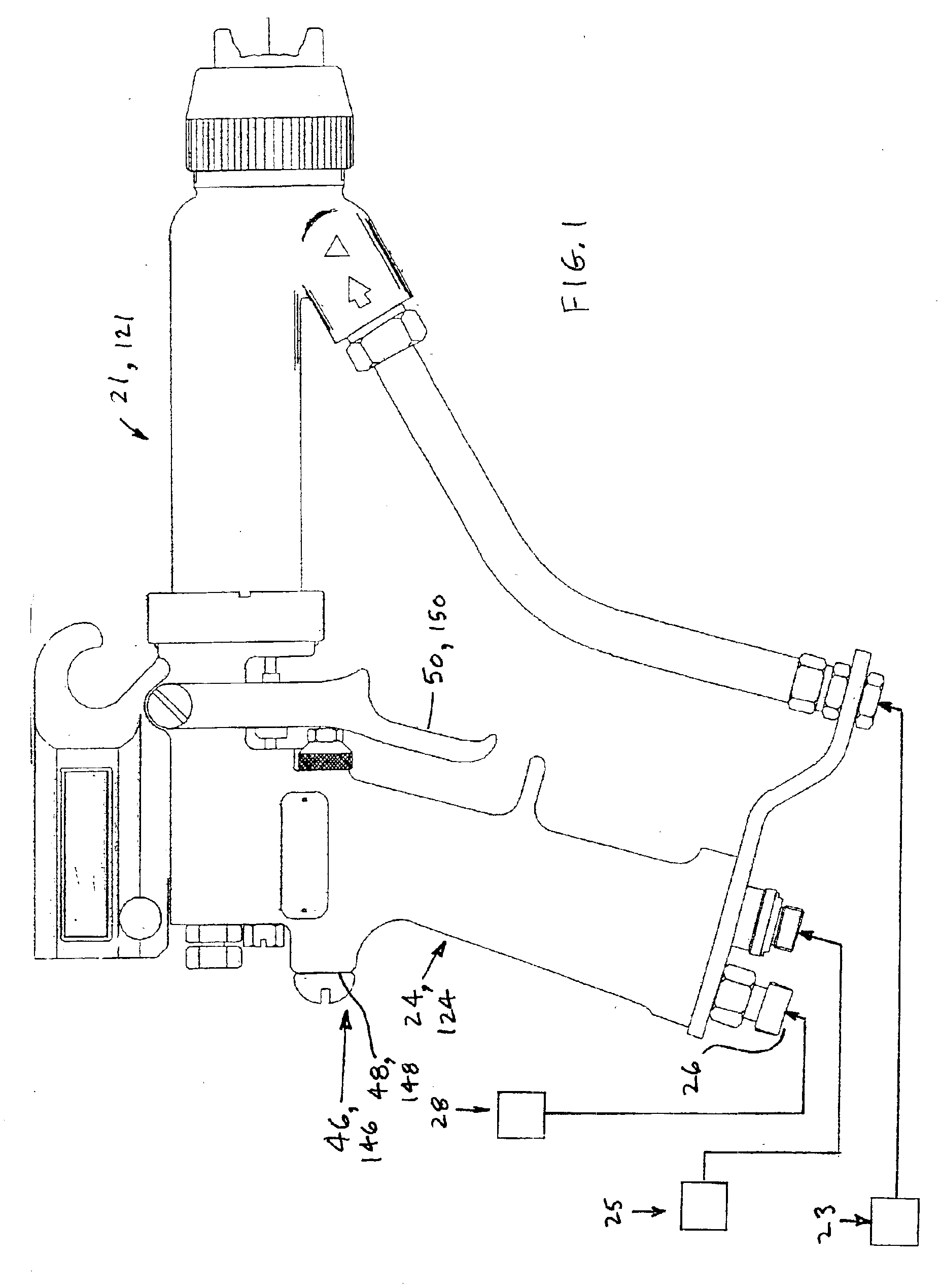
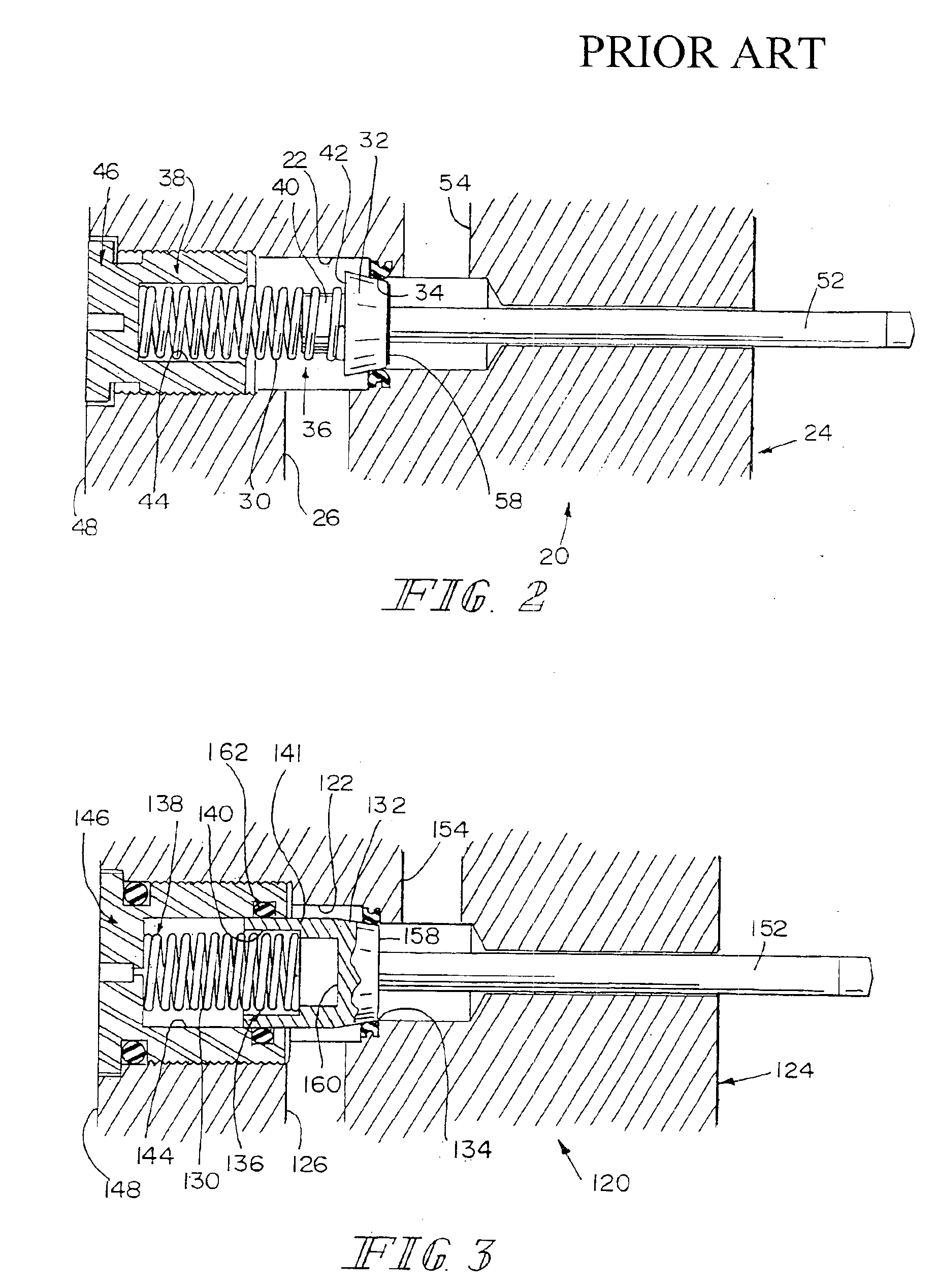
A prior art air valve 20 is illustrated in FIG. 2. Such valves 20 are used in a number of commercially available liquid coating dispensing guns 21. See FIG. 1. Guns 21 of this general type include, for example, the Ransburg model REA 3, REA 4, REA 70, REA 90, REM and M-90 all available from ITW Ransburg, 320 Phillips Avenue, Toledo, Ohio, 43612-1493. This listing is not exhaustive, as this is a common trigger air valve construction. Typically, gun 21 is coupled through appropriate fittings and the like to a source 23 of coating material to be atomized and dispensed from gun 21, a source 28 of compressed air, and a source 25 of high- or low-magnitude electrical potential, which is used in electrostatic charging and atomization of the coating material. Compressed air from source 28 is used, for example, in the process of atomizing and dispensing the coating material, cleaning the gun 21, and the like. Electrical potential from source 25 is used in electrostatic charging and atomizatio...


PUM


Abstract

A coating material dispensing device includes a port adapted to be coupled to a source of coating material, an actuator for controlling a flow of compressed gas through the dispensing device, and a valve coupled to the actuator to be controlled by the actuator. The valve includes a valve housing, a valve closure member, and a valve seat. The valve closure member is movable in the housing under the control of the actuator between a closed position against the valve seat and an open position away from the valve seat. An inlet port is provided into the housing. The inlet port is oriented on a first side of the valve seat. The inlet port is adapted to be coupled to a source of the compressed gas. An outlet port is provided on the second side of the valve seat. The valve closure member includes a first surface which faces generally in a first direction of movement of the valve closure member away from the valve seat and a second surface which faces generally in a second direction of movement of the valve closure member toward the valve seat.

Description

FIELD OF THE INVENTIONThis invention relates to a valve structure. It is disclosed in the context of a structure for an air valve for a dispensing device, such as a handheld coating material dispensing device, sometimes referred to hereinafter as a handgun or gun. However, it is believed to have other applications as well.BACKGROUND OF THE INVENTIONHandheld coating material dispensing devices of various types are well-known. There are, for example, the guns illustrated and described in U.S. Pat. Nos. 3,169,882; 4,002,777; and, 4,285,446. There are also the Ransburg model REA 3, REA 4, REA 70, REA 90, REM and M-90 guns, all available from ITW Ransburg, 320 Phillips Avenue, Toledo, Ohio, 43612-1493. No representation is intended by this listing that a thorough search of all material prior art has been conducted, or that no better art than that listed is available. Nor should any such representation be inferred.DISCLOSURE OF THE INVENTIONAccording to an aspect of the invention, a coati...

Claims


Application Information

Patent Timeline
IPC IPC(8): B05B7/02B05B7/12B05B5/025
CPCB05B7/12B05B5/025B05B7/1209
Inventor ALLEN, HAROLD T.
Owner CARLISLE FLUID TECH INC
Why Eureka
Try Eureka