Staple puller with pliers for removing stragglers

Active Publication Date: 2005-02-15
WOOD LAWSON A
View PDF5 Cites 3 Cited by
  • Summary
  • Abstract
  • Description
  • Claims
  • Application Information

AI Technical Summary

Benefits of technology

The object of the present invention is to provide an inexpensive staple puller with built-in

Problems solved by technology

FIG. 2 illustrates a problem that sometimes occurs during this process.
This is what I call a “straggler.” An attempt to remove a straggler with one's fingers

Method used


Image

  • Staple puller with pliers for removing stragglers
  • Staple puller with pliers for removing stragglers

Examples


Example

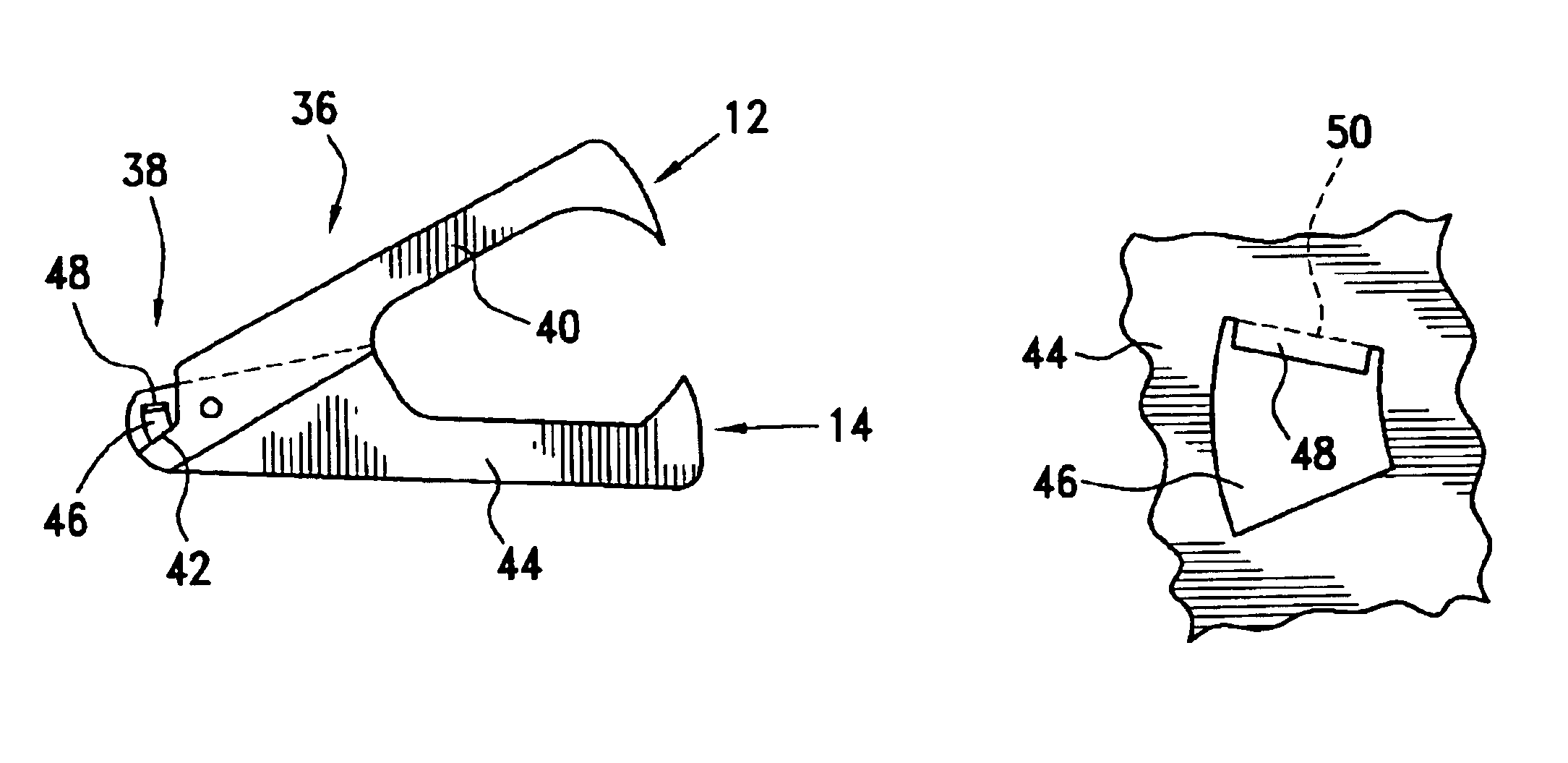
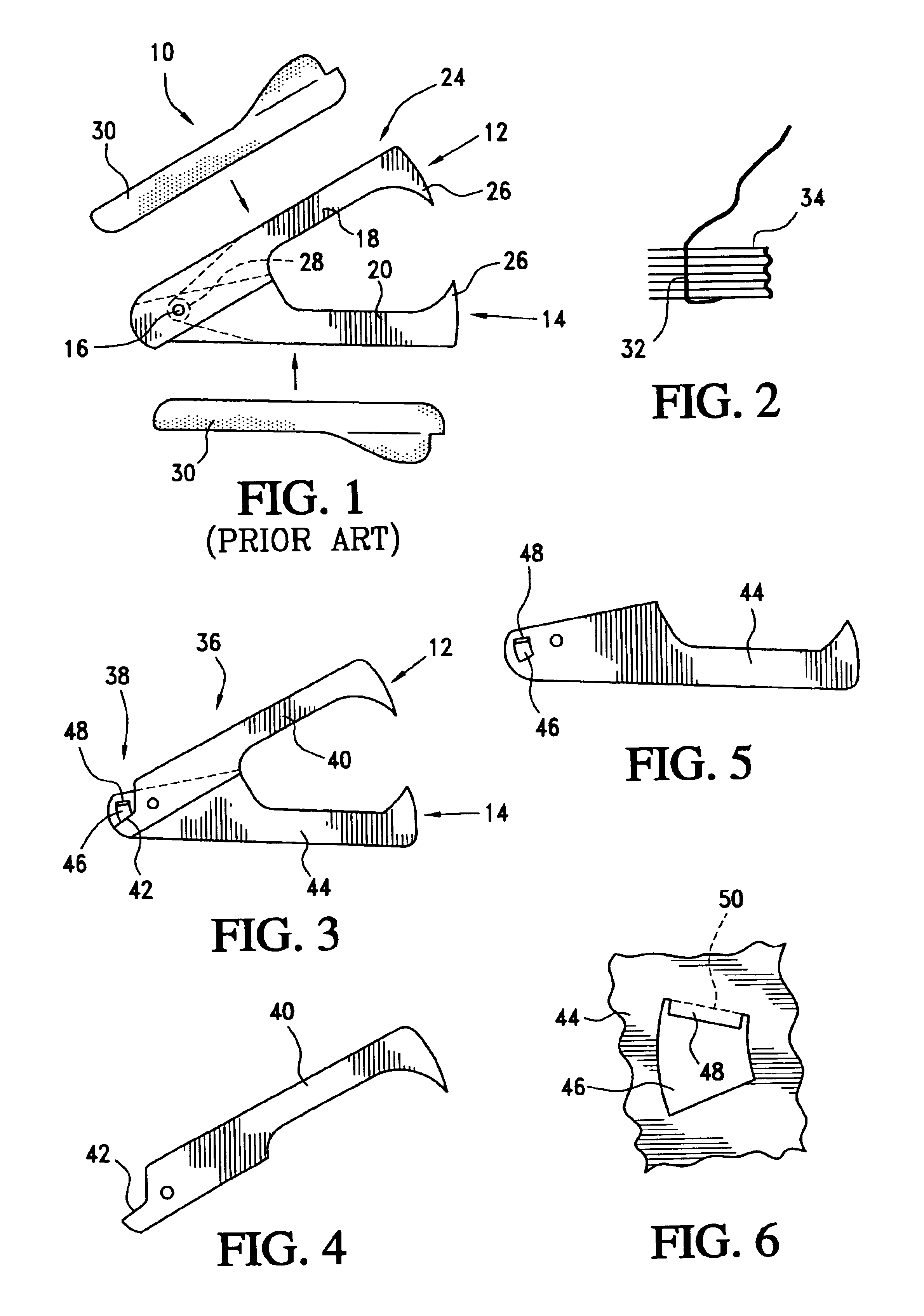
The right side of an improved staple puller 36 in accordance with the present invention is shown (without its finger grips 30) in FIG. 3. Its construction is the same as that of the staple puller 10 shown in FIG. 1, except at the back end portion 38. The left side wall 40 of the first jaw member 12 is shown in FIG. 4, and includes a clamping surface 42. The left side wall 44 of the second jaw member 14 is shown in FIG. 5. It includes a slot 46 with a bent-out flange 48 at the slot's upper end. The flange 48 provides a clamping surface that is positioned to meet the clamping surface 42 when the staple puller 36 is moved to its closed position. The clamping surfaces 42 and 48 act as the jaws of pliers to grip a straggler that has been inserted through the slot 46, so that the straggler can be pulled out.

FIG. 6 illustrates a small part of the side wall 44 during manufacture of the jaw member 14. When the slot 46 is punched out, a tab of sheet metal is left extending into the slot. This...


PUM


Abstract

A staple puller includes a pair of pivotably connected jaw members that are made from sheet metal. The jaw members have teeth that are configured to hook under a staple and pull it from a stack of pages. But sometimes one leg of a staple remains embedded in the stack after the other leg is pulled free, thus producing a “straggler” that may be difficult to remove if the stack is relatively thick. Accordingly, one of the jaw members is provided with a bent flange that cooperates with an edge of the other jaw member in the manner of pliers so that a straggler can be gripped and pulled out.

Description

BACKGROUND OF THE INVENTIONThe present invention is directed to an improved staple puller for removing wire staples from pages of paper. More particularly, the invention is directed to a staple puller that is provided with clamping surfaces for gripping the wire of a staple that has one leg removed from the pages and the other leg still embedded in the pages, so that the embedded leg can be pulled free.FIG. 1 illustrates a left side view of a conventional staple puller 10. It includes a first jaw member 12, a second jaw member 14, and a rivet 16 that extends through holes in the members 12 and 14 to pivotably join them together. The jaw members 12 and 14 are made from sheet metal and are generally U-shape in cross-section. That is, the jaw member 12 includes a left side wall 18, a right side wall (not shown) having the same shape as the wall 18, and a back wall (not shown) that joins the left and right side walls. Similarly, the jaw member 14 includes a left side wall 20, a right si...

Claims


Application Information

Patent Timeline
IPC IPC(8): B25C11/02B25C11/00
CPCB25C11/02
Inventor WOOD, LAWSON A.
Owner WOOD LAWSON A
Why Eureka
Try Eureka