Retractable rod assembly

a technology of rods and components, applied in the direction of rod connections, fastening means, constructions, etc., can solve the problems of reducing the precision of positioning and the service life of the positioning device b>20/b> being relatively shor

Inactive Publication Date: 2005-02-15
HSIEH DAVID
View PDF19 Cites 121 Cited by
  • Summary
  • Abstract
  • Description
  • Claims
  • Application Information

AI Technical Summary

Benefits of technology

The positioning device includes a mounting block and a pair of spring-loaded retainers. The mounting block is disposed in the inner tube, and is formed with a pair of retainer passages that are respectively aligned with the first and second inner radial holes. Each of the spring-loaded retainers, which are disposed respectively in the retainer passages, includes a retaining pin and a biasing member for biasing the retaining pin to extend out of a respective one of the first and second inner radial holes and into a respective one of the first and second outer radial holes to releasably secure the outer and inner tubes in the extended state.

Problems solved by technology

Furthermore, the V-shaped leaf spring 21 easily suffers from elastic deformation, and the precision of positioning will decrease such that the service life of the positioning device 20 is accordingly relatively short.

Method used


Image

  • Retractable rod assembly
  • Retractable rod assembly
  • Retractable rod assembly

Examples


Embodiment Construction

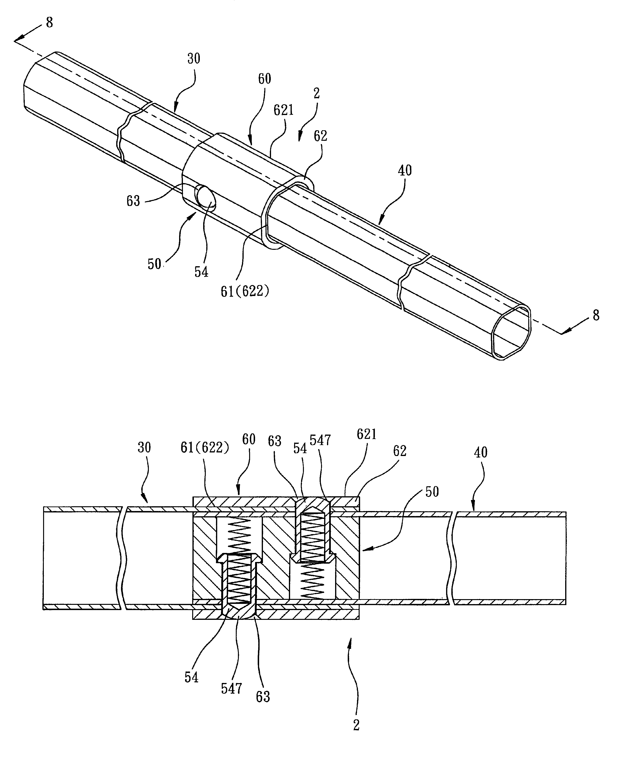
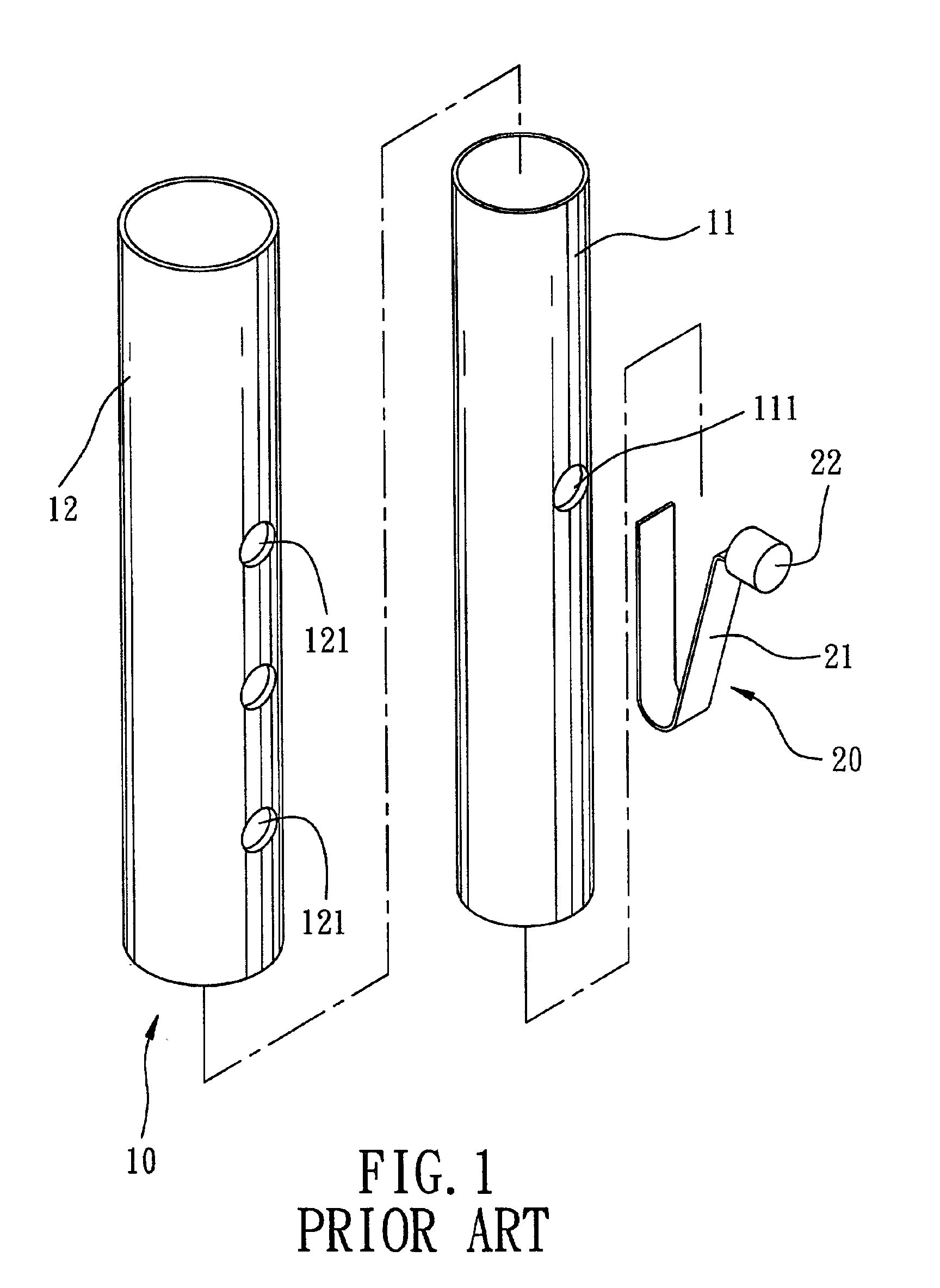
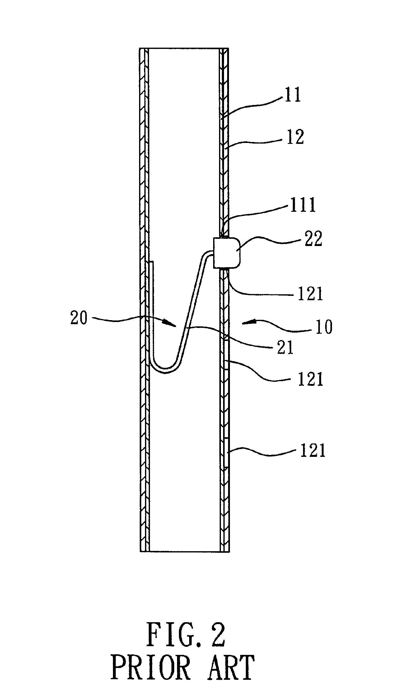
Referring to FIGS. 4, 5 and 6, the first preferred embodiment of a retractable rod assembly 1 according to the present invention is shown to comprise an outer tube 30, an inner tube 40 inserted into the outer tube 30, and a positioning device 50.

The outer tube 30 has an outer tube wall 32 that defines an outer tube axis and that confines an axial tube hole 31 with a non-circular cross-section. The outer tube wall 32 has an outer wall surface 321, and further has first and second outer radial holes 33 formed therein. The first and second outer radial holes 33 form a first angle that ranges from 90 to 180 degrees with respect to the outer tube axis, and are spaced apart from each other by a first distance along the outer tube axis. In this embodiment, the first angle is 180 degrees.

The inner tube 40 has an inner tube wall 42 that defines an inner tube axis, that confines an axial tube hole 41, and that has a non-circular cross-section. The cross-section of the axial tube hole 31 of th...


PUM


Abstract

A retractable rod assembly includes outer and inner tubes, and a positioning device. An outer tube wall of the outer tube has two outer radial holes formed therein. An inner tube wall of the inner tube has two inner radial holes formed therein. The positioning device includes a mounting block and two spring-loaded retainers. The mounting block is disposed in the inner tube, and is formed with a pair of retainer passages respectively aligned with the inner radial holes. Each of the spring-loaded retainers, which are disposed respectively in the retainer passages, includes a retaining pin and a biasing member for biasing the retaining pin to extend out of aligned ones of the inner and outer radial holes to releasably secure the outer and inner tubes in an extended state.

Description

BACKGROUND OF THE INVENTION1. Field of the InventionThe invention relates to a retractable rod assembly, more particularly to a retractable rod assembly having a positioning device that can securely retain outer and inner tubes in an extended state.2. Description of the Related ArtReferring to FIGS. 1, 2 and 3, a conventional telescopic rod 10 is shown to comprise an inner tube 11, an outer tube 12 sleeved on the inner tube 11 and slidable along the length of the inner tube 11, and a positioning device 20 disposed in the inner tube 11. The inner tube 11 is formed with a radial positioning hole 111. The outer tube 12 is formed with a plurality of radial adjusting holes 121 that are spaced apart from each other along the length of the outer tube 12. The positioning device 20 includes a leaf spring 21 disposed in the inner tube 11, and a positioning button 22 mounted on one end of the leaf spring 21. The positioning button 22 extends out of the positioning hole 111 in the inner tube 11...

Claims


Application Information

Patent Timeline
Patent Type & Authority Patents(United States)
IPC IPC(8): F16B7/00F16B7/10
CPCF16B7/105E05Y2800/122Y10T403/32475Y10T403/32508Y10T403/32467Y10T403/32483
Inventor HSIEH, DAVID
Owner HSIEH DAVID
Why Eureka
Try Eureka