Patterned stitch bonded pile fabric

a technology of patterned stitch and pile fabric, applied in the field of stitch bonded materials, can solve the problems of not believing, relatively complex and difficult to carry out, etc., and achieve the effect of substantial fabric integrity

Inactive Publication Date: 2005-02-15
TIETEX INT
View PDF4 Cites 46 Cited by
  • Summary
  • Abstract
  • Description
  • Claims
  • Application Information

AI Technical Summary

Benefits of technology

The present invention provides advantages and alternatives over the prior art by providing a method for forming a patterned pile fabric directly on a stitch bonding machine wherein intricate designs may be produced using a ground yarn system in combination with a pile yarn system without the need for substantial subsequent patterning processes. The resulting pile fabrics may find uses in any number of applications including residential and / or automotive upholstery wherein substantial fabric integrity is required.

Problems solved by technology

While such techniques have been useful, they have nonetheless been relatively complex and difficult to carry out due to the need to use specialized equipment to carry out the patterning procedures.
While it has been possible to use such stitch bonding techniques to form substantially uniform pile surfaces, it is not believed that structures using multiple yarn systems to impart intricate patterns of raised and lowered surfaces has been used in the past.

Method used


Image

  • Patterned stitch bonded pile fabric
  • Patterned stitch bonded pile fabric
  • Patterned stitch bonded pile fabric

Examples


example 1

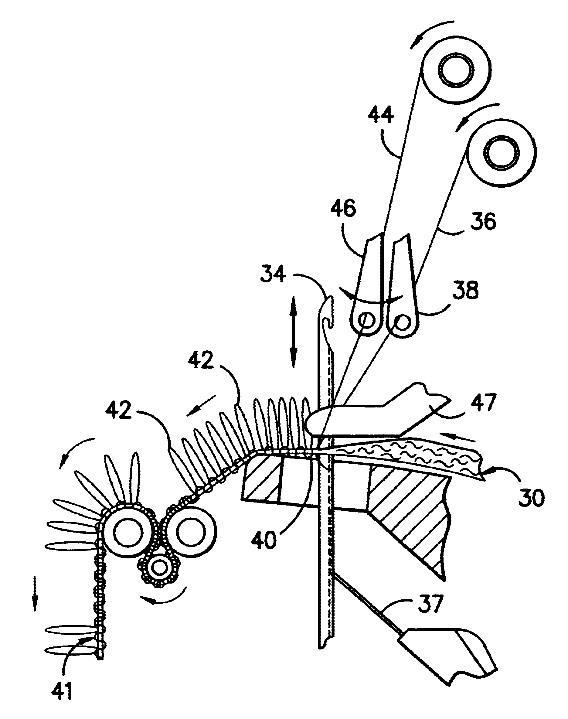
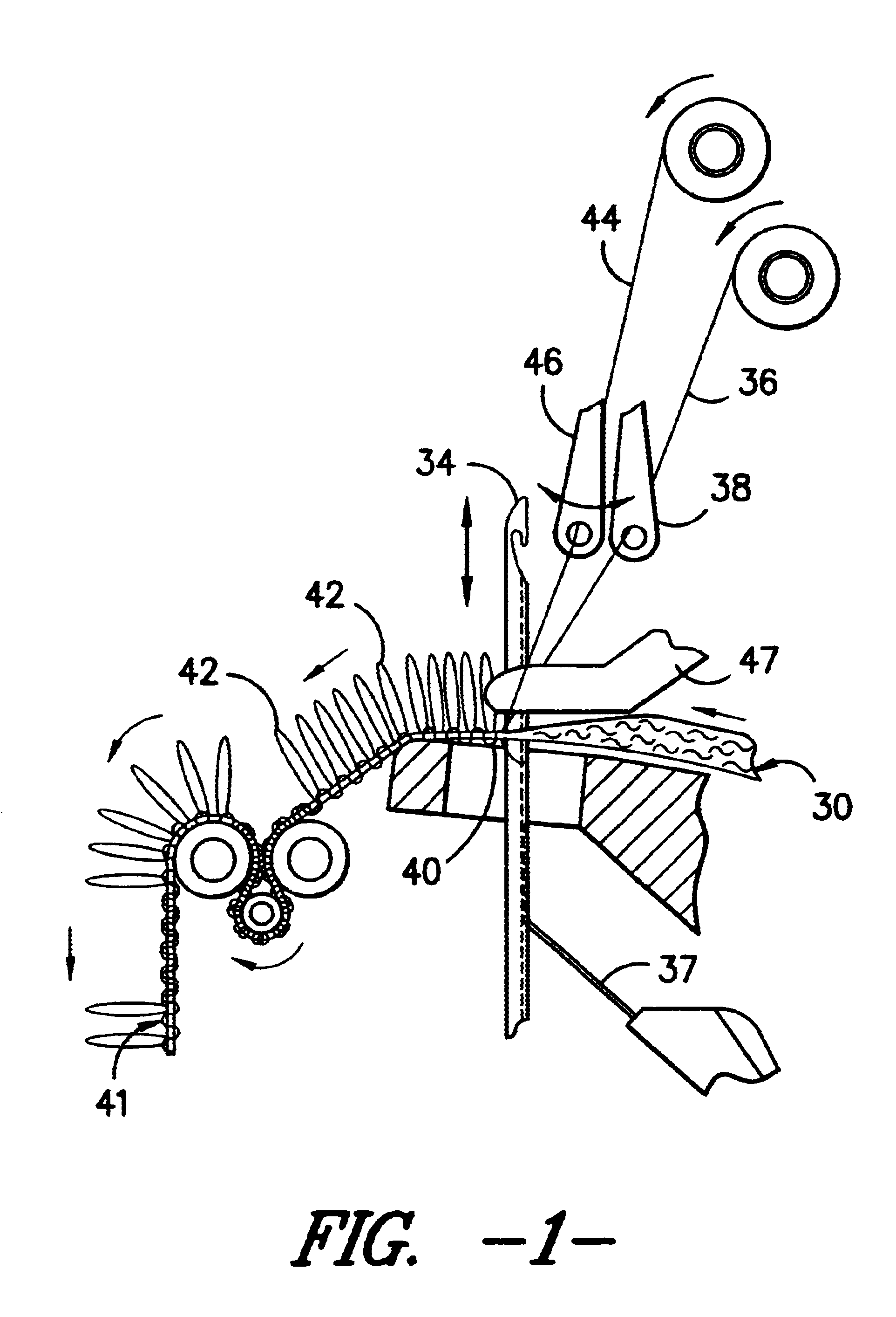
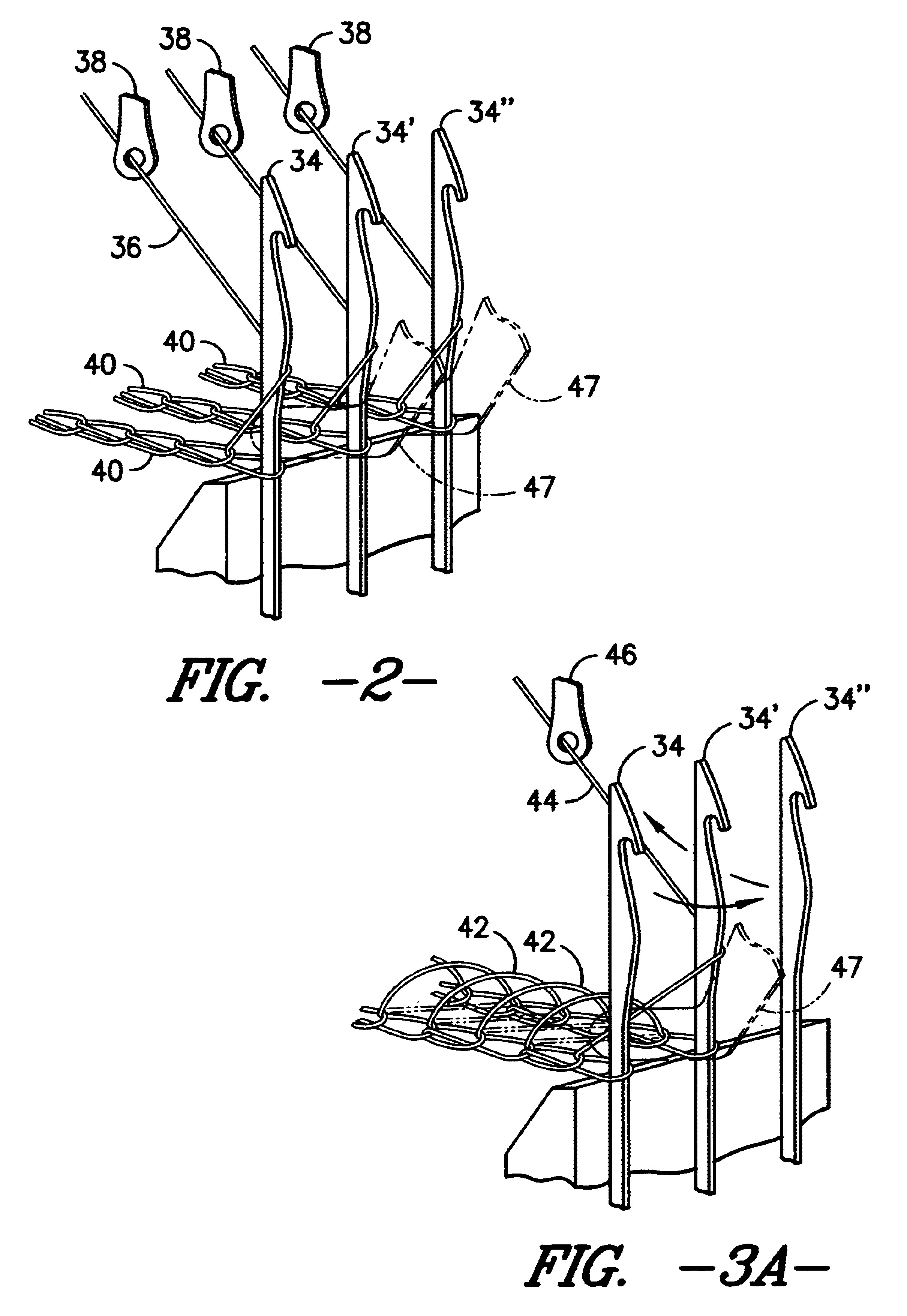
A Liba type stitch-bonding machine having a construction of similar to that illustrated in FIG. 1 was used to form an upholstery fabric. In the formation, a carded and cross lapped fleece substrate formed of 97% recycled polyester staple and about 3% core / sheath polyester bi-component staple including a low melting point polyester sheath constituent was passed to the stitch bonding machine. The fleece had a width of approximately 120 inches and a mass per unit area of approximately 90 grams per square meter. A polyester ground yarn of multi-filament construction having a linear density of approximately 70 denier was applied in a fully threaded chain stitch in substantially covering relation to the fleece. Concurrently with the stitching of the ground yarn, a multi-filament polyester pile yarn having a linear density of approximately 150 denier was applied in a selected patterned arrangement through the substrate. The pile yarn was threaded in a 3 inch repeat pattern through yarn gui...

example 2

The procedures of Example 1 were repeated in all respects except that the pile yarn was threaded through guide elements in a 5 inch repeat pattern and was selectively shogged to yield a stitch notation of 3-4, 3-2, 2-1, 1-0, 0-1, 1-0, 1-2, 3-3 / / . The resulting patterned pile fabric is illustrated in FIG. 6.


PUM

PropertyMeasurementUnit
linear densitiesaaaaaaaaaa

Abstract

A patterned pile fabric of stitch-bonded construction. The fabric includes a substrate layer with an arrangement of ground yarns extending in stitched relation through the substrate layer so as to define a ground covering across the substrate layer. An arrangement of pile forming yarns extend in stitched relation through the substrate layer such that the pile forming yarns define a patterned arrangement of looped elements projecting away from the ground covering in predefined three dimensional patterned arrays disposed across the fabric.

Description

TECHNICAL FIELDThe present invention relates to stitch bonded materials and more particularly to stitch bonded materials having a multi-yarn stitch system incorporating yarns stitched through a fibrous substrate so as to define a pattern of raised and lowered pile surfaces across the fabric.BACKGROUND OF THE INVENTIONPile fabrics in general are well known and typically include a plurality of pile yarns tufted through or bonded to a substrate such as a scrim layer. By way of example only, one prior known technique for forming a pile fabric has been to pass pile yarns back and forth between opposing substrate layers so as to form a coordinated structure and to thereafter slit the formed structure between the substrate layers so as to yield a free-standing pile surface extending away from each of the substrate layers. Patterning across the pile surface may thereafter be carried out by various means including shaving, impingement by hot air so as to selectively melt outstanding pile yar...

Claims


Application Information

Patent Timeline
Patent Type & Authority Patents(United States)
IPC IPC(8): B32B3/06B32B3/02B32B5/02B32B33/00D04H3/02D04H3/05D04H1/54D04B21/14
CPCD04B21/04Y10T428/24033Y10T428/23979Y10T442/681Y10T442/697Y10T442/692Y10T442/682Y10T428/23936Y10T442/643Y10T428/23929Y10T442/69Y10T428/23957D04B23/08D04B27/06D04B21/165
Inventor WILDEMAN, MARTINFONTAINE, ROBERT
Owner TIETEX INT
Why Eureka
Try Eureka