
Cam-type retainer clip for heat sinks for electronic integrated circuits

a technology of electronic integrated circuits and retainer clips, which is applied in the direction of machine supports, furniture parts, lighting and heating apparatus, etc., can solve the problems of retainer clips being unloosed, retainer clips may be prone to loosening, and retainer clips may be easy to loosen, etc., to achieve low cost, substantial assembly integrity, and easy assembly

Inactive Publication Date: 2004-12-28
PSC COMP PRODS
View PDF17 Cites 16 Cited by
  • Summary
  • Abstract
  • Description
  • Claims
  • Application Information

AI Technical Summary

Benefits of technology

It is an object of the present invention to overcome the above stated difficulties of the prior art devices so as to provide a retainer clip and heat sink assembly which is low in cost, easy to assemble, has substantial assembly integrity, is relatively impervious to adverse environmental conditions affecting the electronic device in which the heat sink assembly is used, and is inexpensive to fabricate.

Problems solved by technology

In all of the above-described devices, a common problem is the cost of the retainer clip and, much more importantly, the labor required to properly attach the retainer clip to secure the heat sink to the semiconductor chip and / or socket.
Other problems include design of a retainer clip so that there is a positive and easily recognized proper engagement of the retainer clip.
The result is that when the computer or other electronic device is shipped, and is subjected to various forces, shaking, vibration, and other environmental shipping conditions the retainer clip may be unloosed with the result that the heat sink becomes disengaged and can ruin other components within the electronic device as the device is continued to be roughly handled in shipping.
Even if other components are not damaged, with the heat sink dislodged, there being little likelihood that the user will be aware of such problem, the semiconductor device can be easily overheated and damaged or destroyed.
Still another problem with prior art devices is the cost of the retainer clip itself.
Many proposed prior art devices require complex machining operations which greatly increase the price of the clip.
Wires are particularly unsuitable for the construction of retainer clips; although they are simple in appearance, the bending and forming of wire is a more complex and expensive forming operation than simple stamping.
Other prior art devices use molded plastic and / or metal parts that must be cast or forged which again are more expensive metal forming operations.
Another problem with prior art retainer clips again relates to the rough handling that occurs during shipping of electronic devices which contain a semiconductor device, heat sink and retainer clip.
However, with a sharp blow in the plane of the surfaces, such as the acceleration that may be experienced during some sudden starting or stopping of the electronic device in which this assembly is contained, the heat sink may slide relative to the chip and then strike the retainer clip holding means so as to dislodge the clip and again allowing the heat sink to be separated from the chip and heat sink assembly.
Even partial movement of the heat sink base relative to the semiconductor device so that the heat sink is still in engagement with the semiconductor device but is displaced will affect the efficiency of the heat transfer from the device to the heat sink.

Method used


Image

  • Cam-type retainer clip for heat sinks for electronic integrated circuits
  • Cam-type retainer clip for heat sinks for electronic integrated circuits
  • Cam-type retainer clip for heat sinks for electronic integrated circuits

Examples


first embodiment

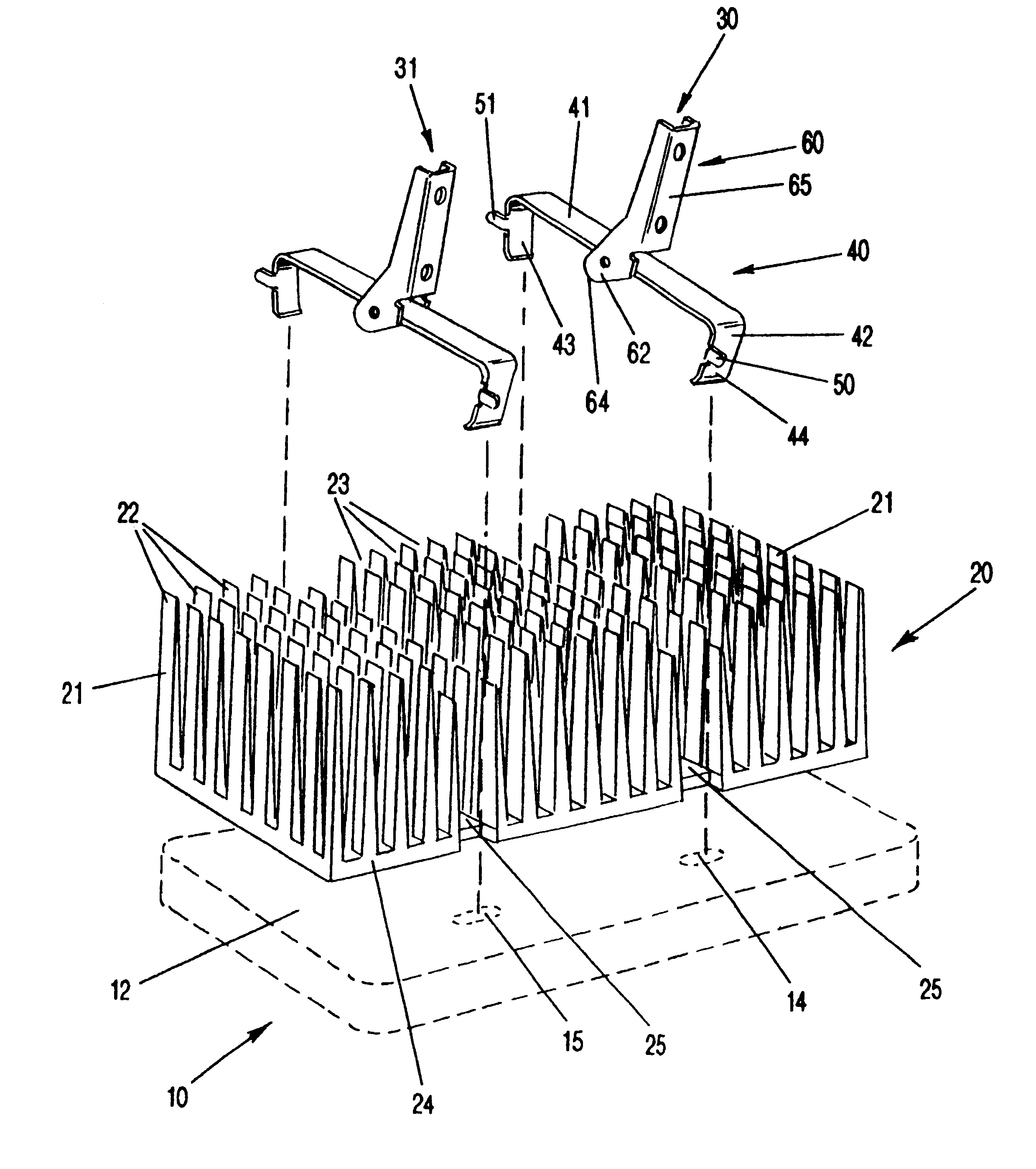
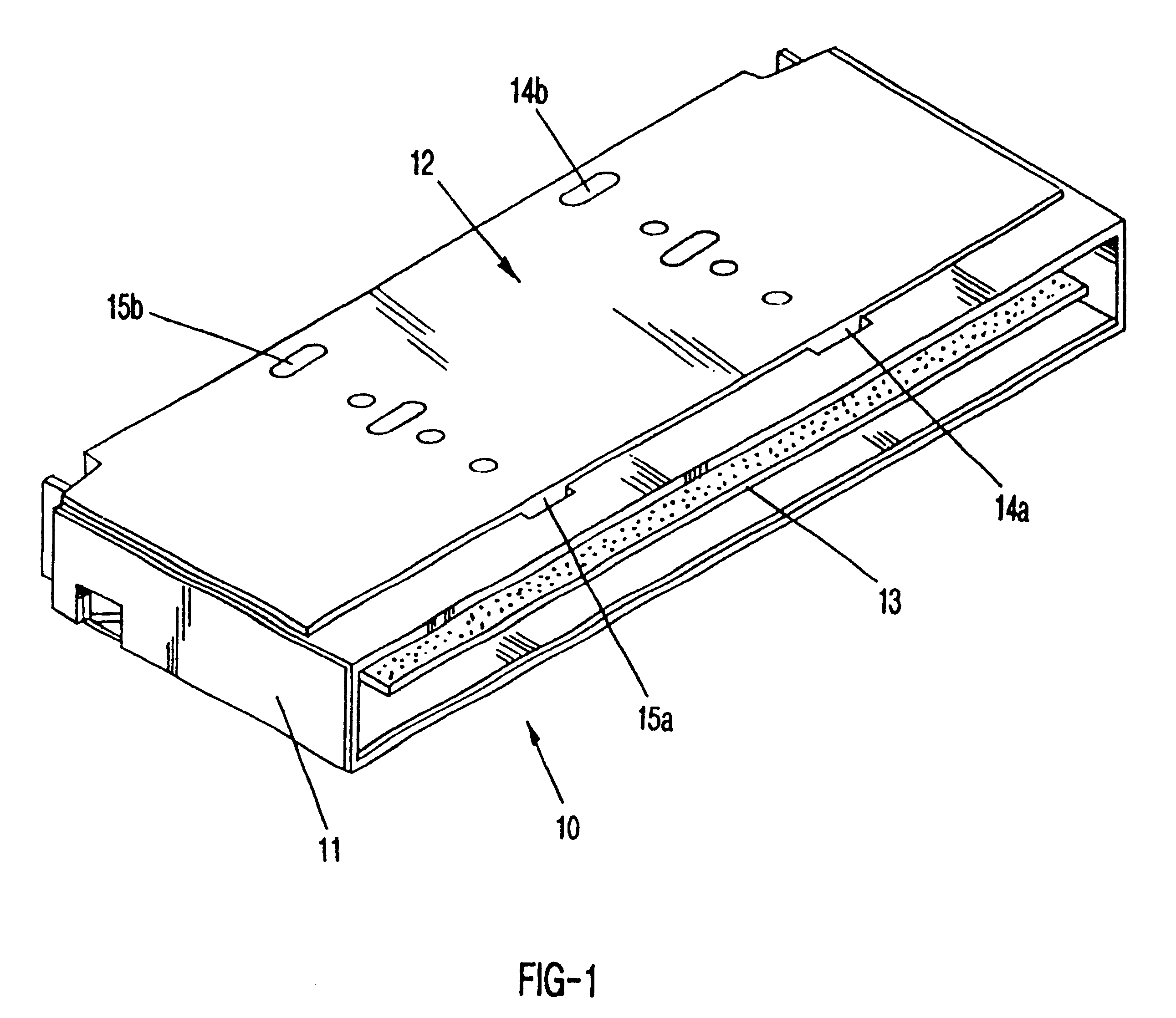
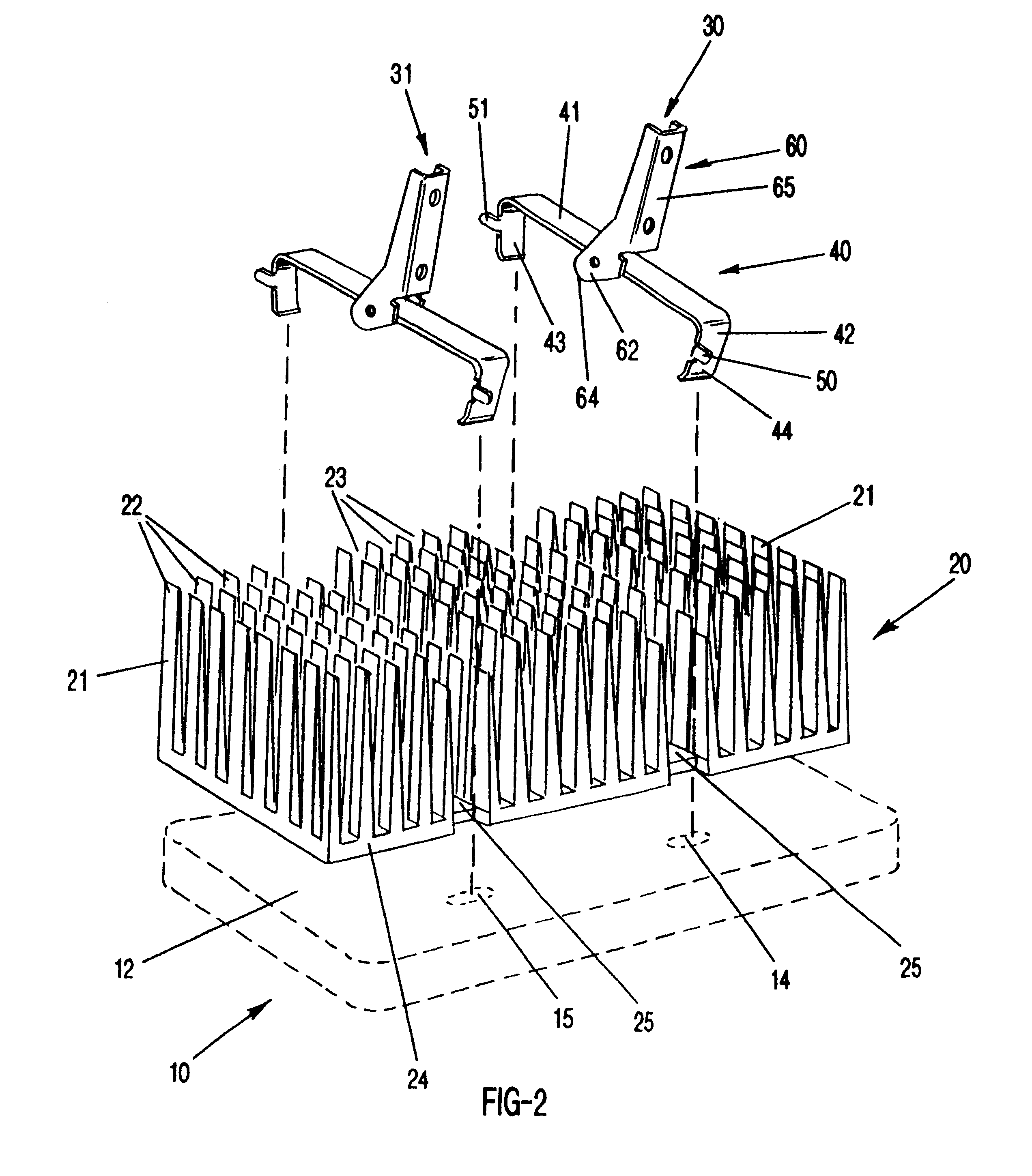
the present invention will be shown and described in conjunction with a semiconductor module 10 which has a case 11 including a wall 12 defining the upper surface of case 11. The module is merely representative of a housing that contains at least one semiconductor device; the term "housing" includes modules, cartridges, the semiconductor device itself, or the semiconductor device mounted in a socket. Within the module is mounted a printed circuit board 13 which may include one or more semiconductor devices (not shown). A portion of the upper major wall 12 is made of metal or other high heat-conducting material and is intended to engage or interface with a heat sink for dissipating heat from the semiconductor devices and the module as a whole. To assist in the engagement of a heat sink to the wall 12, the major wall 12 is provided with a plurality of openings shown at 14 and 15. In the particular module configuration shown, two holes 14A, 15a are adjacent one longitudinal edge and tw...


PUM


Abstract

A heat sink assembly comprises a heat sink and a retainer clip for attachment to an electronic package or semiconductor device so as to dissipate heat from such device. The heat sink may comprise a flat base with a plurality of upwardly extending fins. The fins will define at least one channel. The retainer clip includes two parts. One part is an elongated, resilient, metal strap that has holding means at each end for engaging a semiconductor socket, or a semiconductor module, so as to secure the retainer clip and heat sink to the device or module. The retainer clip also includes a cam-type latch which is pivotally positioned in the middle of the elongated strap and includes an arm and a cam. The cam has a bearing surface which is spaced from the axis of the elongated member a distance greater than the distance between the elongated member and the upper surface of the heat sink base when in the initially assembled position. When the arm is rotated, the bearing surface of the cam is forced against the upper surface of the heat sink which causes the strap to be displaced upwardly placing pressure on the strap and thereby forcing the heat sink into heat conducting engagement with the electronic device or module.

Description

BACKGROUND OF THE INVENTION1. Field of the Invention (Technical Field)This invention relates to cooling of electronic assemblies.Since the successful introduction of integrated circuits (ICs), there has been a steady progression toward larger IC devices to permit inclusion of a greater number of functions on the IC. The result is that the heat produced by these larger semiconductor devices is not adequately removed by either natural air convection nor by powered ventilation, such as a fan.Convection cooling is performed by use of a heat sink that is directly applied to the semiconductor device. It is not desirable to use a bonding process, such as an adhesive, because of the permanent nature of such attachment; a semiconductor device may be discarded if malfunctioning and it is not desirable to throw away the heat sink too. It has therefore been found desirable to attach the heat sink to the chip or device by mechanical means such as a retainer clip. The typical heat sink currently ...

Claims


Application Information

Patent Timeline
Patent Type & Authority Patents(United States)
IPC IPC(8): H05K7/20H01L23/367H01L23/40
CPCH01L23/3677H01L23/4093H01L2924/0002Y10T24/308Y10T24/44026H01L2924/00
Inventor BLOMQUIST, MICHAEL L.
Owner PSC COMP PRODS
Learn More