Time-delay integration in electrophoretic detection systems

a detection system and time delay technology, applied in the field of electrophoretic detection systems, can solve the problems of large power consumption, inefficient energy consumption, and high cost of laser equipmen

Inactive Publication Date: 2005-02-15
APPL BIOSYSTEMS INC
View PDF42 Cites 66 Cited by
  • Summary
  • Abstract
  • Description
  • Claims
  • Application Information

AI Technical Summary

Problems solved by technology

Unfortunately, laser apparatuses are expensive to use, energy inefficient, consume large amounts of power, and are physically large, rendering electrophoretic systems incorporating lasers cumbersome to use.
Although the use of light emitting diodes (LED's) for generating fluorescence in dye molecules is taught, for example, in U.S. Pat. Nos. 6,005,663 and 5,710,628, the contents of which are incorporated herein in their entireties by reference, the use of LED's in such electrophoretic methods typically results in low signal strengths and detection sensitivity that is only marginal.
The low signal strength tends to impair adequate detection of marker compounds.
Electrophoresis arrangements that employ complex optics causing a reduction of the collecting efficiency of the detector also result in low sensitivity.
The low sensitivity is aggravated through the use of LED's, which compromise sensitivity in the first instance.
The problem of lowered sensitivity through LED use is further exacerbated when using multiple-channel-type electrophoretic devices, that is, electrophoretic devices using an etched plate with capillary-sized grooves, or using a plurality of capillary tubes, where either type of device has multiple-channels used to increase throughput.

Method used


Image

  • Time-delay integration in electrophoretic detection systems
  • Time-delay integration in electrophoretic detection systems
  • Time-delay integration in electrophoretic detection systems

Examples


Embodiment Construction

The apparatuses and methods herein can address the need for an electrophoresis device and process that employs a cost-effective and convenient source of irradiation. Various embodiments can be especially well suited for multiple-channel electrophoretic systems used to increase throughput.

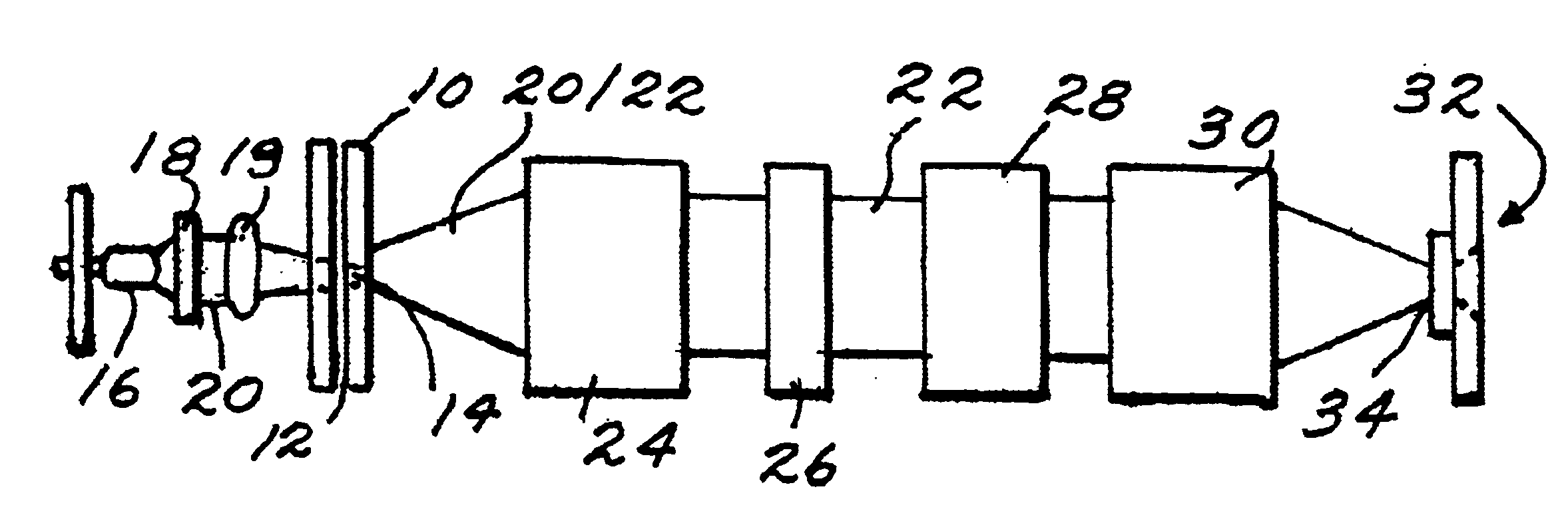
FIG. 1 shows an exemplary embodiment of an electrophoresis device. As depicted in FIG. 1, the arrangement can include a channel-defining member 10 defining a channel 12 therein for the migration of an analyte sample. The channel-defining member 10 may include a cover plate with or without grooves, an etched plate defining one or more capillary sized grooves therein, or one or more capillary tubes. According to various embodiments, the channel-defining member can be an etched plate having a plurality of channels or grooves, or the channel-defining member can include a plurality of capillary tubes. The use of a plurality of channels can allow a large number of analyte samples to be measured simultaneo...


PUM

PropertyMeasurementUnit
fluorescence emission peak intensityaaaaaaaaaa

Abstract

An apparatus for detecting analytes in a sample is provided. The apparatus includes: one or more channels having a detection zone; one or more irradiation sources disposed for irradiating the detection zone with non-coherent radiation; a detector array disposed for collecting light signals emitted from markers in the detection zone excited by the radiation, the detector array having an output; and a system coupled to the detector array for effecting time delay integration of the charges on the detector array corresponding to the light signals by accumulating the charges before reading the charges at the output of the detector array. Other apparatus and methods for detecting analytes in a sample are also provided.

Description

FIELD OF THE INVENTIONThe various embodiments relate to electrophoretic detection systems, and, in particular, to arrangements and methods for light detection during electrophoresis.BACKGROUND OF THE PRESENT INVENTIONWell-known examples of biopolymer analysis using DNA sequencing are taught, for example, in F. Sanger, et. al., DNA Sequencing with Chain Terminating Inhibitors, 74 Proc. Nat. Acad. Sci. USA 5463 (1977); Lloyd M. Smith, et. al., Fluorescence detection in automated DNA sequence analysis, 321 Nature 674 (1986); Lloyd M. Smith, The Future of DNA Sequencing, 262 Science 530 (1993). These and all other publications and patents cited herein are incorporated herein in their entireties by reference.Known capillary electrophoresis systems and methods can require laser-induced fluorescence for exciting marker compounds or markers, such as dye molecules typically used to label analytes. Unfortunately, laser apparatuses are expensive to use, energy inefficient, consume large amount...

Claims


Application Information

Patent Timeline
Patent Type & Authority Patents(United States)
IPC IPC(8): G01N27/447G01N21/64
CPCG01N27/44721
Inventor NORDMAN, ERIC S.REEL, RICHARD T.SHIGEURA, JOHN
Owner APPL BIOSYSTEMS INC
Why Eureka
Try Eureka