Fiber optic cable closure and assembly

a fiber optic cable and enclosure technology, applied in the direction of fibre mechanical structures, electric cable installations, instruments, etc., can solve the problems of time-consuming and cumbersome process, inconvenient use or prevention,

Inactive Publication Date: 2005-02-15
PREFORMED LINE PROD CO
View PDF18 Cites 43 Cited by
  • Summary
  • Abstract
  • Description
  • Claims
  • Application Information

AI Technical Summary

Benefits of technology

Another advantage of the present invention is the provision of a splice tray which has members which are slidable and lock into place in a pivoted position to allow access to lower splice trays in a stacked relationship.
is the provision of a splice tray which has members which are slidable and lock into place in a pivoted position to allow access to lower splice trays in a stacked relationship.
Still yet another advantage of the present invention is the provision of a fang-shaped bracket which has flexible prongs which allow wrapping of the cable within the closure and maintains the cable within the closure.
Still other advantages and benefits of the invention will become apparent to those skilled in the art upon a reading and understanding of the following detailed description.

Problems solved by technology

These prior enclosures are satisfactory to a greater or lesser degree but often have certain limitations which make them inconvenient to use or prevent them from being readily adaptable to changing environments and conditions.
This proves to be a time consuming and cumbersome process.

Method used


Image

  • Fiber optic cable closure and assembly
  • Fiber optic cable closure and assembly
  • Fiber optic cable closure and assembly

Examples


Embodiment Construction

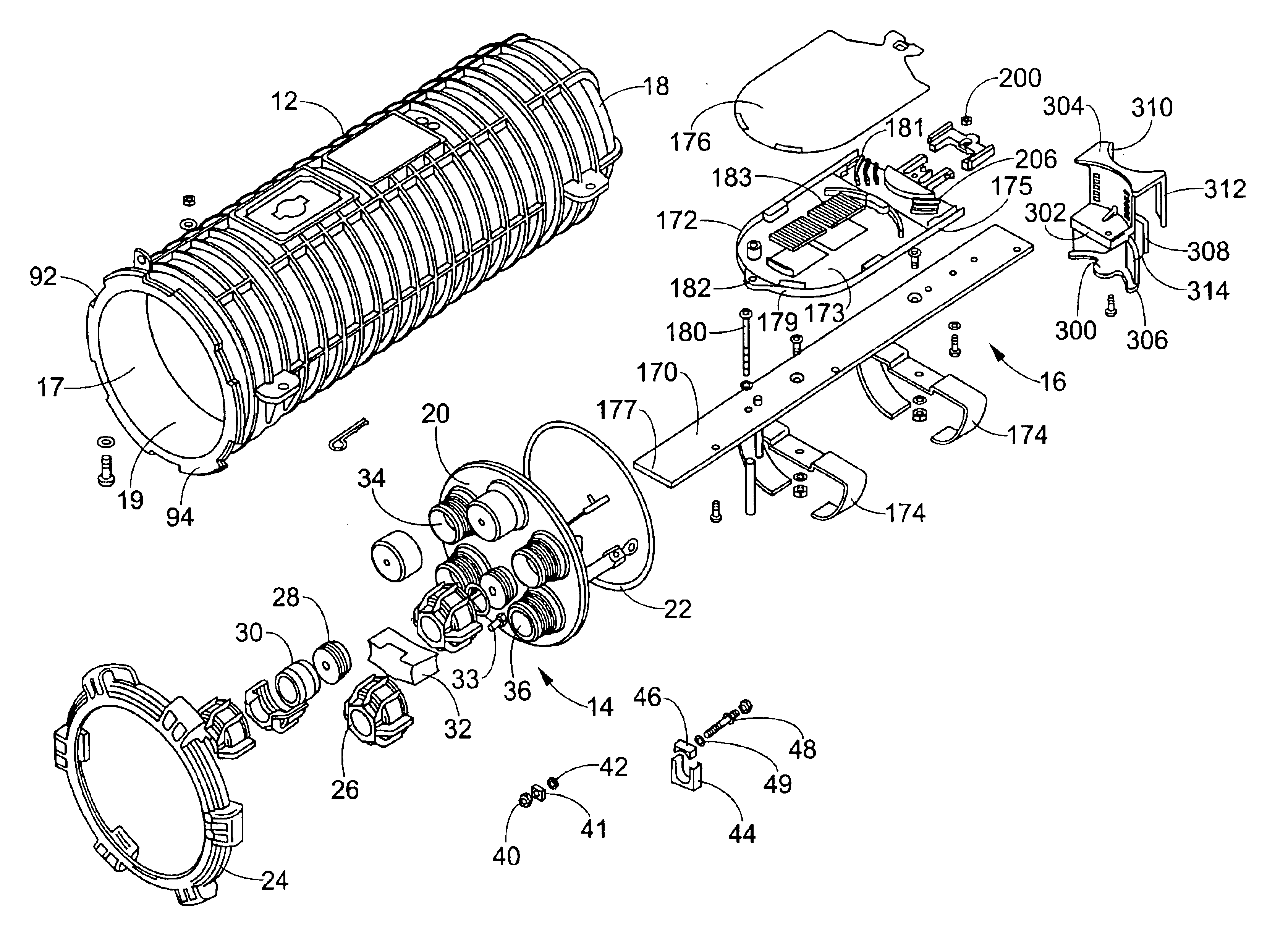
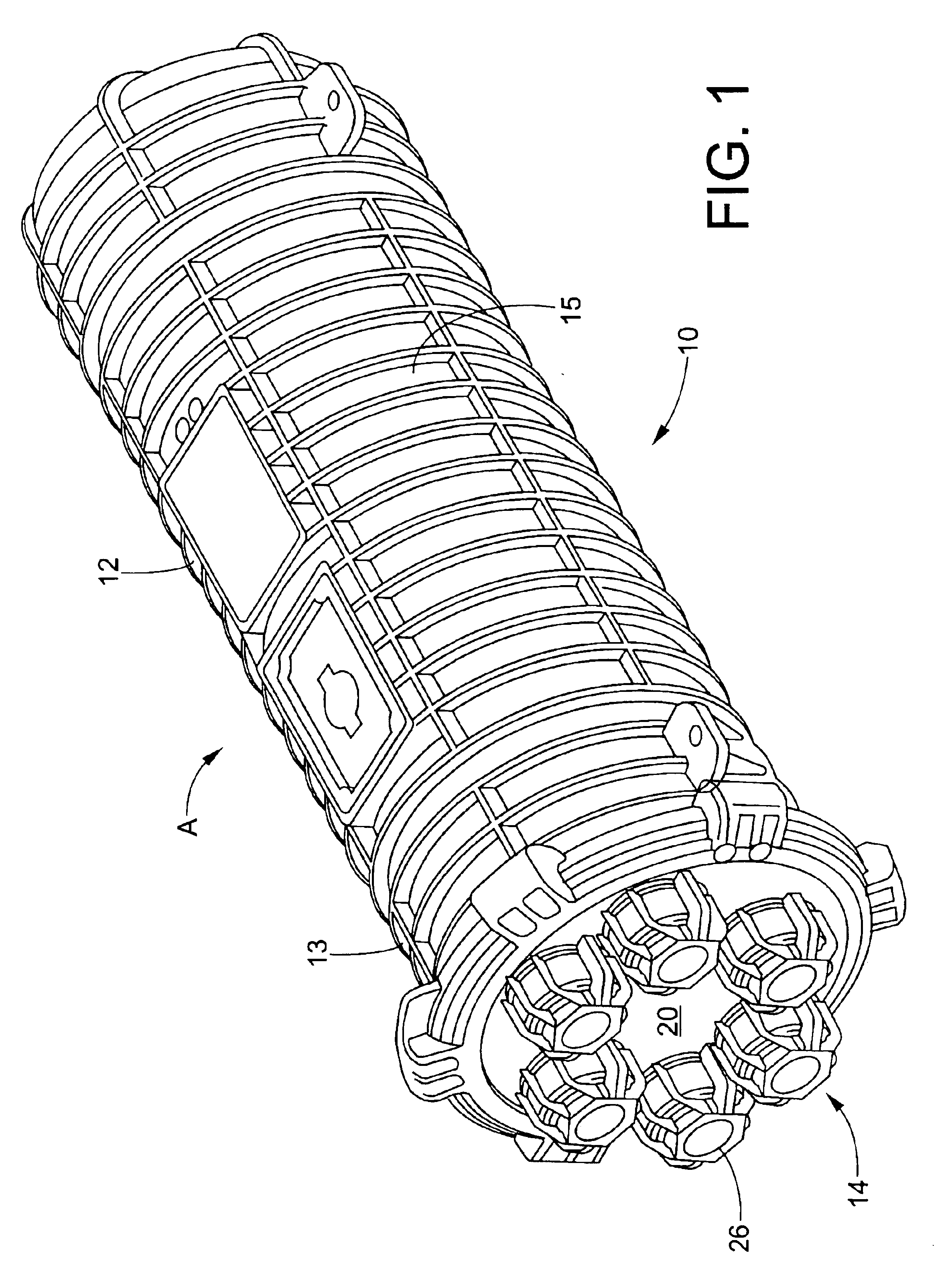
Referring to the drawings, wherein the showings are for purposes of illustrating the preferred embodiments of the invention only, and not for purposes of limiting same, FIG. 1 shows a fiber optic cable closure system A in accordance with a first embodiment of the present invention.

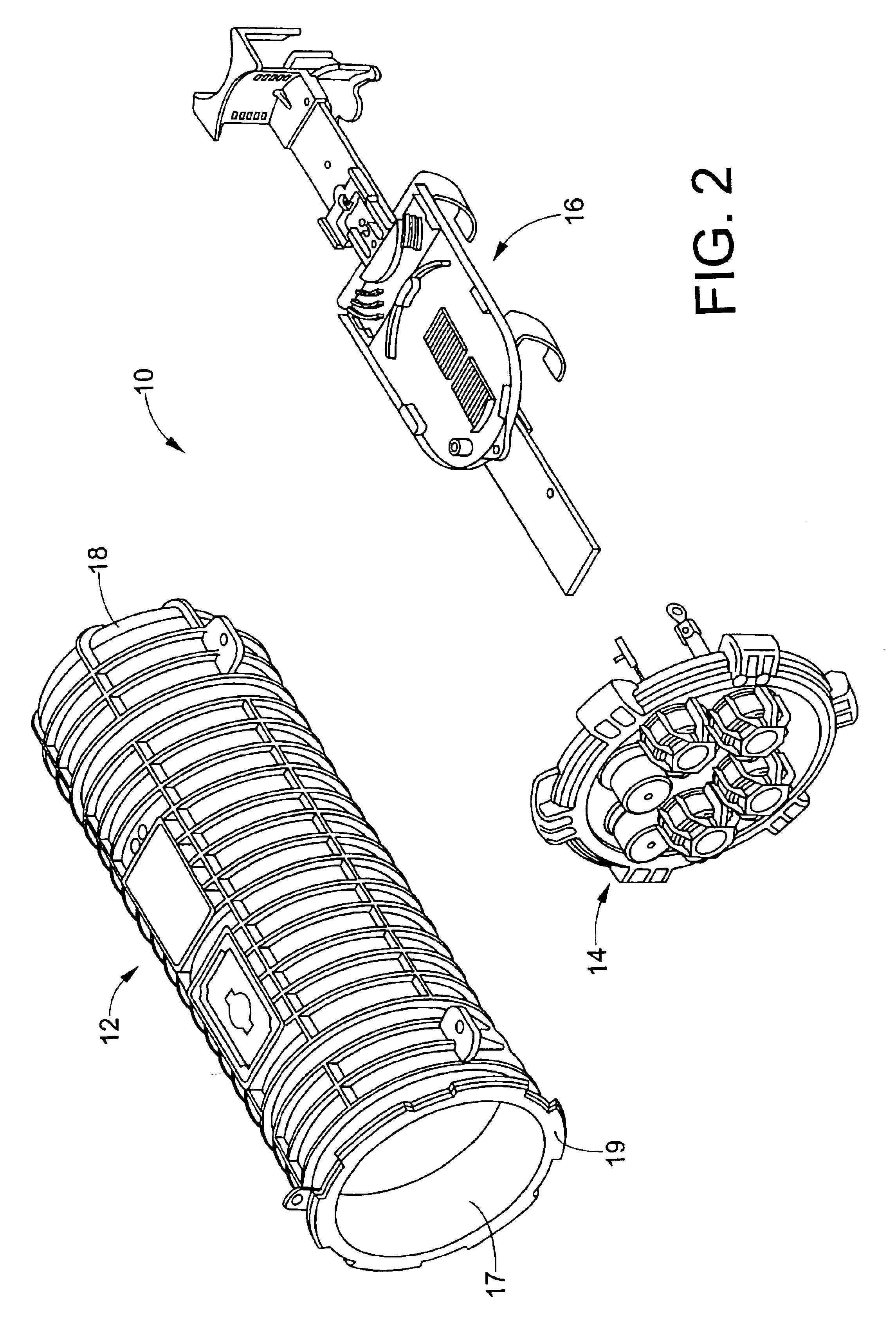
With particular reference to FIGS. 1 and 2, cable closure 10 includes a main body preferably in the form of a dome member 12, an end plate assembly 14 removably securable to the dome 12, and a splice tray management assembly 16 removably securable to the end plate assembly 14. The dome 12 forms an elongated, generally cylindrical housing which has a plurality of radially extending ribs 13 formed on an outer surface 15 thereof. In the embodiment being described, the dome is a unitary, one-piece structure with an open, first end 17, a closed, second end 18, and an internal cavity 19. The internal cavity can be sealed, pressurized, and / or potted as desired to protect the splice tray management assembly 16.

Alt...


PUM


Abstract

A cable closure assembly includes a rotatable collar secured to an end plate for rotating the end plate with respect to the closure. Drop ports and express ports are provided within the end plate to accommodate either cut or uncut cables within the closure. Grommet and cap tools are provided which consist of two pieces to be installed over cables after the cables are inserted into the closure. A modular closure system is provided including a dome closure and extender or expander closures to increase storage and splicing area within the dome closure. A sliding and locking bracket allows for movement and pivoting of splice trays to access splice trays below other stacked trays. An extender for a strength member bracket accommodates various lengths of strength members on the cable fiber cable. A bracket on an end of a rigid bar member permits wrapping of the cable within the closure and positions the cable within the closure.

Description

BACKGROUND OF THE INVENTIONThe present invention is directed to a cable splice enclosure assembly. Assemblies of the type under consideration are particularly suited for enclosing and housing fiber optic splice cables, and the invention will be described with particular reference thereto; however, the apparatus could equally well be used with other types of cables.Many different types of cable enclosures are known in the prior art. These prior enclosures are satisfactory to a greater or lesser degree but often have certain limitations which make them inconvenient to use or prevent them from being readily adaptable to changing environments and conditions. It is, accordingly, a primary object of the present invention to provide a cable enclosure assembly that is easy to assemble and use and which can be modified or adapted for different size cables and can be formed in a variety of different sizes that allow the size and number of splices to vary. In addition, the present invention pr...

Claims


Application Information

Patent Timeline
Patent Type & Authority Patents(United States)
IPC IPC(8): G02B6/44
CPCG02B6/4444H02G15/076H02G3/22
Inventor CLOUD, RANDY G.MILLER, KEITH A.MURES, MARCEL G.GARCIA, JOSE ANTONIO RIVERO
Owner PREFORMED LINE PROD CO
Why Eureka
Try Eureka