Camera with light emission function, camera part inspection apparatus, camera adjustment apparatus, and camera part unit

a technology of camera parts and functions, applied in the direction of camera body details, instruments, printing, etc., can solve the problems of increasing the size of the camera, insufficient effect in some cases, and difficult to obtain a picture with a natural sense, so as to improve the red-eye reduction effect and ease the feeling of discomfor

Inactive Publication Date: 2005-02-15
OLYMPUS CORP
View PDF7 Cites 13 Cited by
  • Summary
  • Abstract
  • Description
  • Claims
  • Application Information

AI Technical Summary

Benefits of technology

In view of the above-described problems, it is a feature of the present invention to provide: a camera with a light emission function which can cause an object to pay attention to the camera or a light emission portion for a red-eye reduction function when taking a picture and before flash light emission in particular and thereby improve the red-eye reduction effect, obtain a certain degree of the red-eye reduction effect without selecting a strong red-eye reduction function, enable a portrait with a further natural facial expression by easing a feeling of discomfort with respect to stimulation to eyes when the strong red-eye reduction function is selected, and avoid confusion of light emission as the red-eye reduction function and light emission in clocking of a self-timer, notify not only a camera operator but also an object of an operation state of the camera, e.g., end of a shooting preparation operation after power ON; a camera part inspection apparatus utilizing a technique of a camera with such a light emission function; a camera adjustment apparatus; and a camera part unit.
As described above, according to the present invention, when taking a picture and before flash light emission in particular, an object can be caused to pay attention to the camera or the light emission portion for the red-eye reduction function, thereby improving the red-eye reduction effect.
In addition, it is possible to take a portrait picture with a further natural facial expression by obtaining a certain degree of the red-eye reduction effect without selecting the strong red-eye reduction function and easing a feeling of discomfort with respect to stimulation to eyes when the strong red-eye reduction function is selected.
Additionally, it is possible to avoid confusion of light emission as the red-eye reduction function and light emission for clocking of the self-timer.

Problems solved by technology

However, when such a red-eye prevention apparatus, i.e., an apparatus which performs pre-irradiation before emitting flash light on a object in order to avoid red eyes and a display apparatus which displays a clocking operation state of a self-timer are separately configured in a camera, this leads to an increase in size of the camera.
However, with the camera disclosed in Japanese Patent No. 2532739, since pre-irradiation for reducing red eyes is performed immediately before release, effects tend to be insufficient in some cases.
Furthermore, in cases where the person pays attention to the light emitter, the person as an object feels dazzled when pre-irradiation with a large quantity of light is suddenly performed.
Therefore, the person has a firm facial expression, and it is hard to obtain a picture with a natural sense.

Method used


Image

  • Camera with light emission function, camera part inspection apparatus, camera adjustment apparatus, and camera part unit
  • Camera with light emission function, camera part inspection apparatus, camera adjustment apparatus, and camera part unit
  • Camera with light emission function, camera part inspection apparatus, camera adjustment apparatus, and camera part unit

Examples


Embodiment Construction

Embodiments according to the present invention will now be described hereinafter with reference to the accompanying drawings.

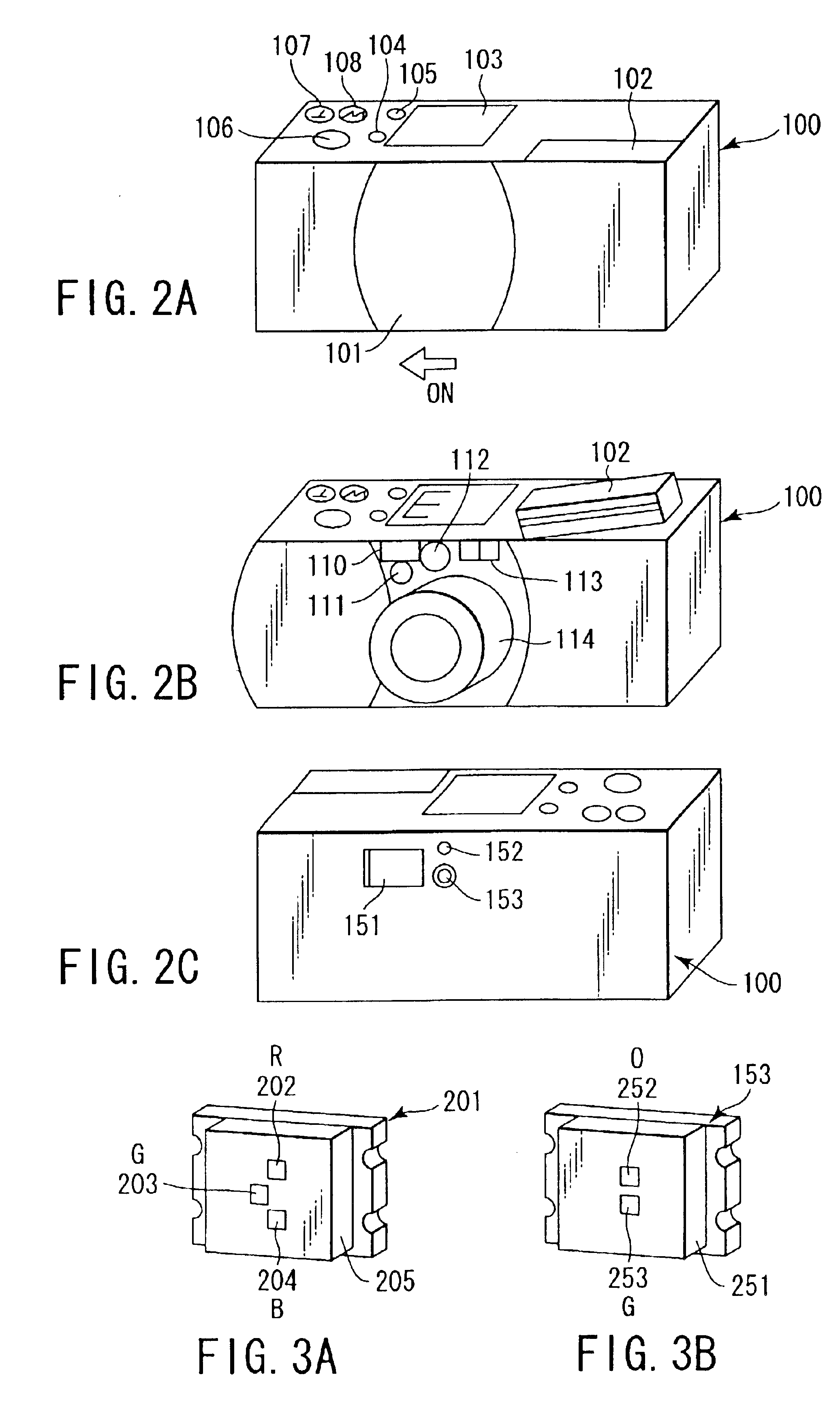
FIG. 2A is an external appearance view of a camera with a light emission function according to an embodiment of the present invention with a lens barrier thereof being closed.

A sliding type lens barrier 101 is provided on the front surface of a camera main body 100. Further, a main switch (which is not shown and will be referred to as a BRSW hereinafter) is turned on by sliding this lens barrier 101 in a direction of an arrow illustrated in the drawing. As a result, the camera enters the operable state.

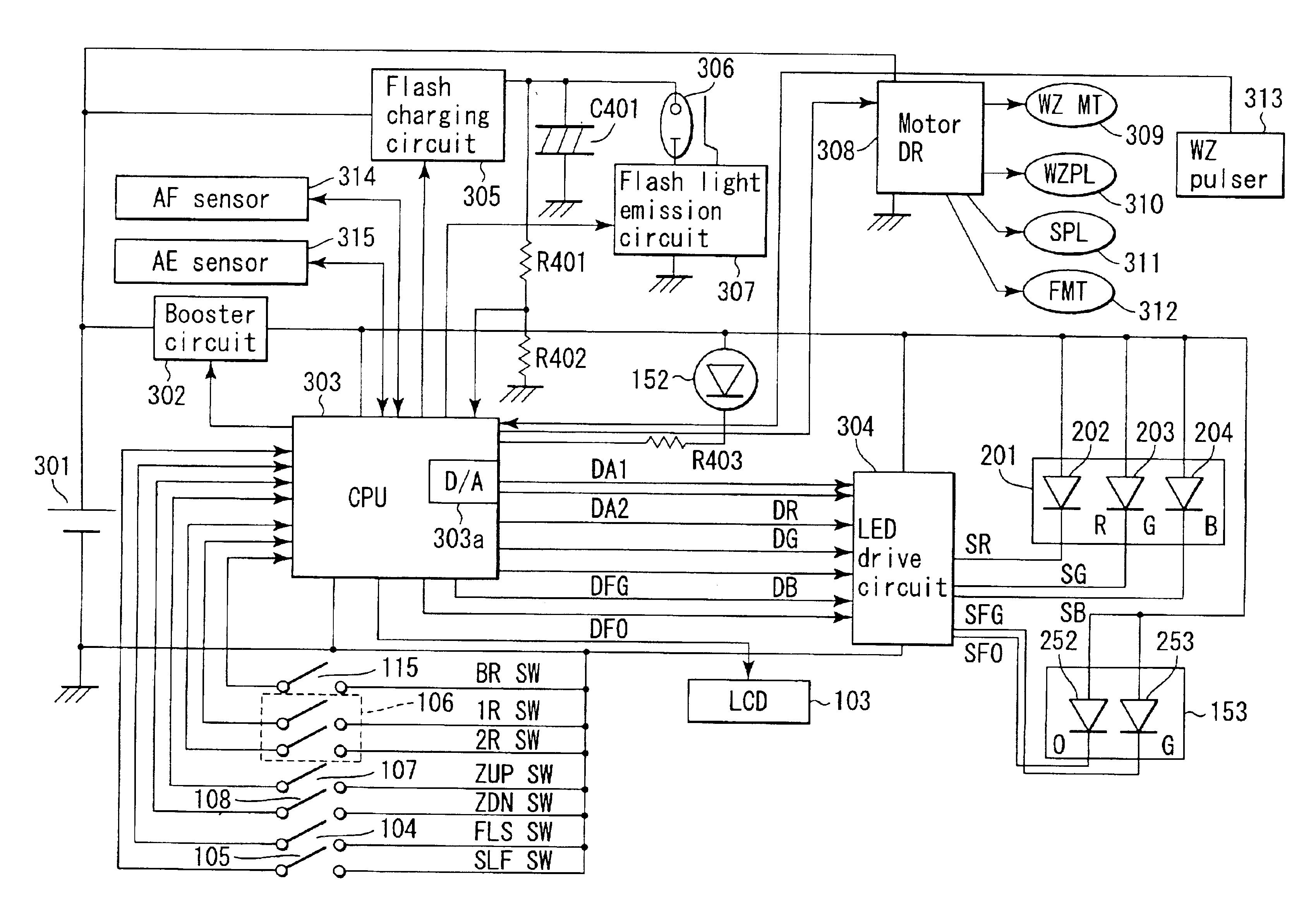
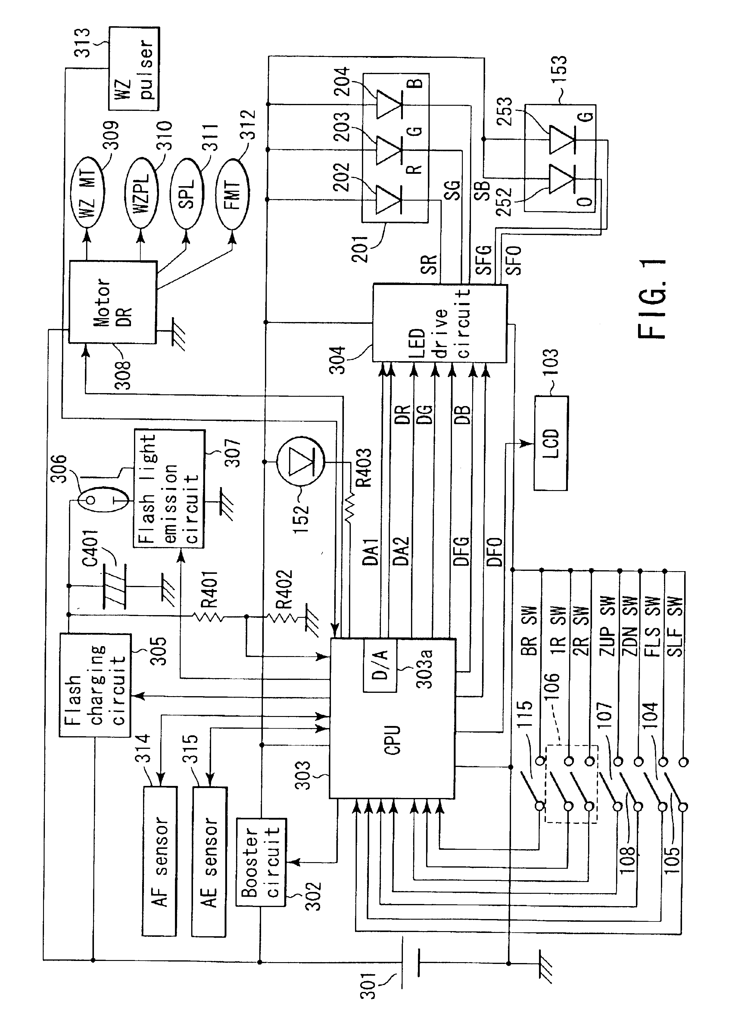
Furthermore, on the top surface of the camera main body 100, a flash device 102, an LCD display unit 103, a flash mode changeover switch (which will be referred to as an FLSSW hereinafter) 104, a self-timer switch (which will be referred to as an SLFSW hereinafter) 105, a release button 106, a zoom-up switch (which will be referred to as a ZUPSW hereinafter) 107...


PUM


Abstract

A CPU judges whether a current operating state of a camera corresponds to an in-service state of a lens barrel or an in-service state of a self-timer, and performs light emission control over a front display LED or a rear display LED by controlling an LED drive circuit. The front display LED or the rear display LED is constituted by integrating LED chips having a plurality of types of colors. Therefore, the front display LED and the rear display LED can emit the light in a plurality of different colors by using one light source.

Description

CROSS-REFERENCE TO RELATED APPLICATIONSThis application is based upon and claims the benefit of priority from the prior Japanese Patent Applications No. 2001-374672, filed Dec. 7, 2001; and No. 2002-022102, filed Jan. 30, 2002, the entire contents of both of which are incorporated herein by reference.BACKGROUND OF THE INVENTION1. Field of the InventionThe present invention relates to a camera with a light emission function which has a function to irradiate an object with light other than flash light before emitting flash light, an apparatus for inspecting parts of a camera having such a light emission function, a camera adjustment apparatus, and a camera part unit.2. Description of the Related ArtThere have been conventionally proposed various kinds of cameras which can prevent a phenomenon that eyes of a person are picturized in red, which is a so-called red-eye phenomenon, when taking a picture of the person as an object by using a flash. Further, on the other hand, there have bee...

Claims


Application Information

Patent Timeline
Patent Type & Authority Patents(United States)
IPC IPC(8): G03B15/05
CPCG03B15/05G03B2215/0507G03B2215/0571
Inventor OKUBO, MITSUMASA
Owner OLYMPUS CORP
Why Eureka
Try Eureka